Eureka AIR delivers breakthrough ideas for toughest innovation challenges, trusted by R&D personnel around the world.

Sheet receiving apparatus

a technology for receiving apparatuses and sheets, applied in the direction of thin material processing, function indicators, printing, etc., can solve the problem of insufficient considerations for improving stacking ability, and achieve the effect of improving the performance of stacking sheets

Inactive Publication Date: 2002-07-02
NISCA KK
View PDF9 Cites 81 Cited by
  • Summary
  • Abstract
  • Description
  • Claims
  • Application Information

AI Technical Summary

Benefits of technology

An object of the invention is to provide a sheet receiving apparatus, which prevents an unnecessary abutment between the stacked sheet and the subsequently ejected sheet, or placing or stacking the sheets in a curled condition in case of stacking the ejected sheets, to thereby improve the performance for stacking the sheets.
Another object of the invention is to provide a sheet receiving apparatus, wherein in order to conduct a predetermined process to the sheet before the sheet is ejected to an outside of the apparatus, even in case of temporarily placing the sheets, a jam caused by collision between the placed sheet and the subsequent sheet is prevented, and the performance of placing the sheet for enabling to securely place the predetermined number of sheets temporarily can be secured.
Still another object of the invention is to provide a sheet receiving apparatus, which can stack or place the sheets by precisely aligning the sheets, and at the same time, which is miniaturized and light-weighed as a whole.
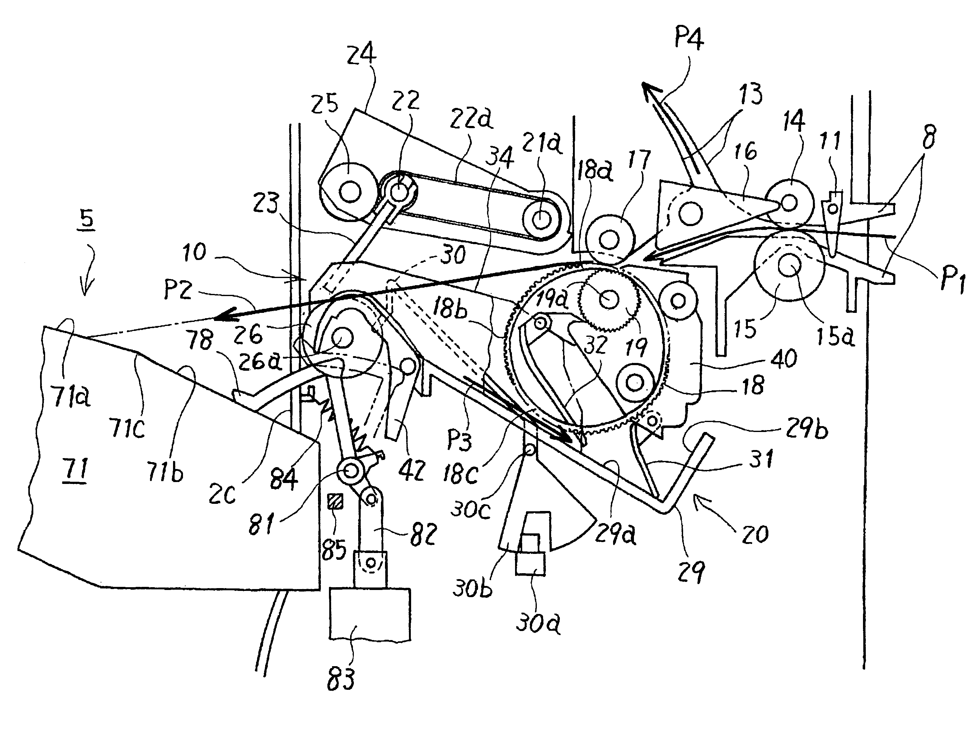
In the sheet receiving apparatus of the invention, also, in order to apply the predetermined processes, such as aligning and binding, to the sheets, before the sheets are completely ejected to the piling stacker, the sheets are temporarily placed on a temporary placing tray located at the upstream side of the sheet ejecting direction. In order to improve an accuracy for aligning and a performance of placing the sheets on the temporary placing tray, sheet transferring means for transferring the sheets on the temporary placing tray is formed of a ring-shaped member flexibly deforming in a thickness direction of the sheets on the temporary placing tray and a crossing direction, respectively, or a transferring unit in which the ring-shaped member is extended between a driving pulley and a driven pulley and which can move in the sheet thickness direction. Also, there is provided aligning means for pressing the sheets, which are transferred onto the temporary placing tray by the transferring means, from the sheet width direction to thereby align the sheets. Then, a positional relationship between the sheet transferring means and the aligning means is structured such that the aligning means regulates a side rim of the sheet at a position where the sheet transferring means contacts the sheet. Incidentally, the arrangement relation, in which the sheet transferring means and the aligning means are overlapped as seen from a direction of the section, contributes to making the apparatus compact.
Further, in order to improve the sheet placing performance in the temporary placing tray, the sheet receiving apparatus of the invention is provided with the sheet pressing means which approaches the upper surface on the temporary placing tray in accordance with the direction of transferring the sheets transferred on the temporary placing tray by the sheet transferring means, and the sheet pressing means is structured to increase the pressing force against the placed sheets in accordance with an increase of the sheets placed on the temporary placing tray.

Problems solved by technology

In the disclosed apparatuses, however, sufficient considerations are not made for improving a stacking ability in case of stacking the sheets, or improving a sheet placement performance in case of temporarily placing the sheets before stacking.
However, in this case, when the forward end of the ejected sheet is ejected in a downward curl in a sheet support surface side, the sheet in a downward curl on the support surface is ejected as it is, so that the sheet is folded and then stacked or placed, resulting in causing the same problem as mentioned above.

Method used


Image

  • Sheet receiving apparatus
  • Sheet receiving apparatus
  • Sheet receiving apparatus

Examples


Embodiment Construction

The present invention relates to a sheet receiving apparatus, in which stacking performance in case of stacking ejected sheets, and placement performance in case of temporality placing the sheets before ejecting the sheets are improved, and an embodiment of the invention is explained with reference to the attached drawings.

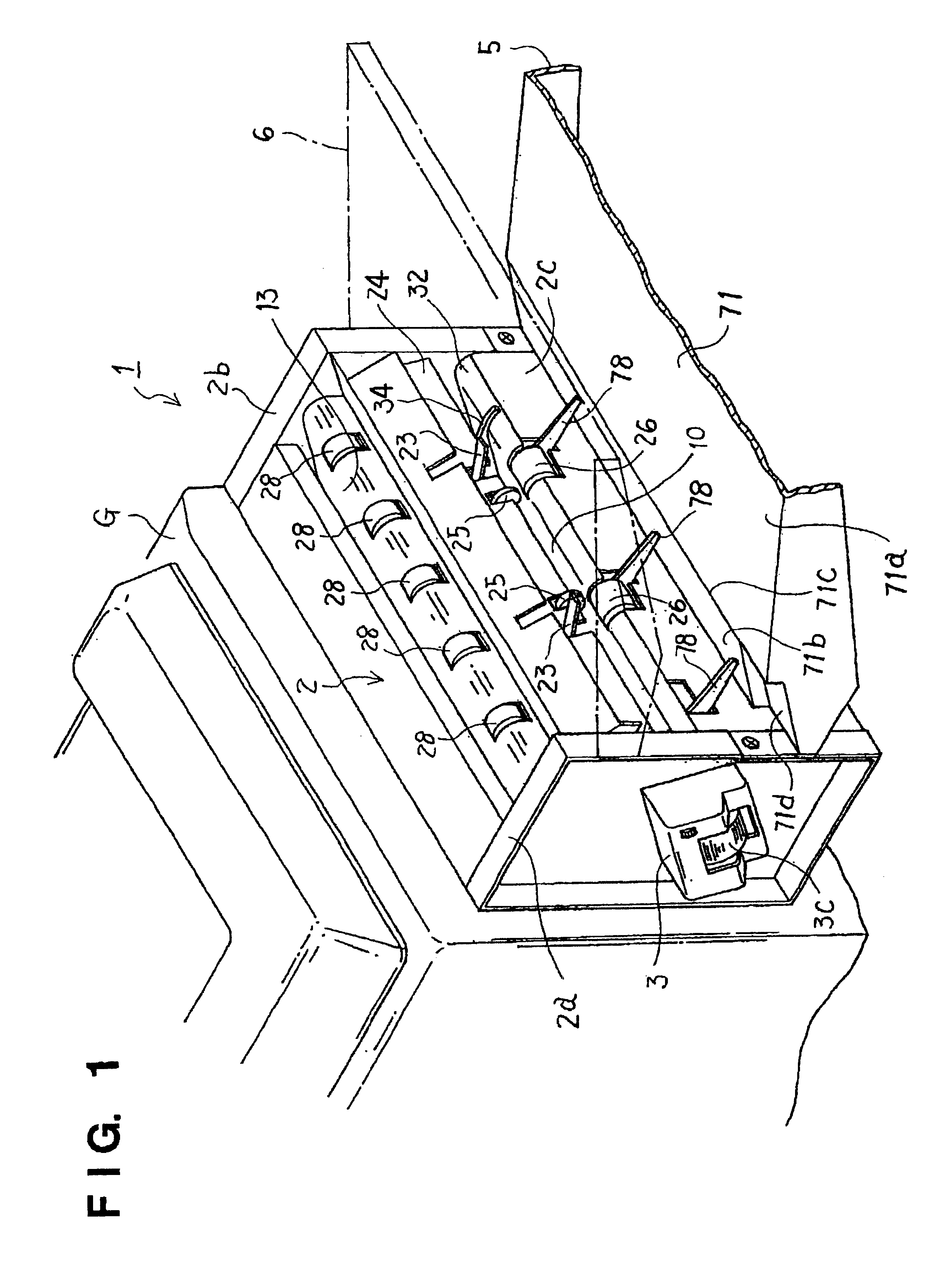
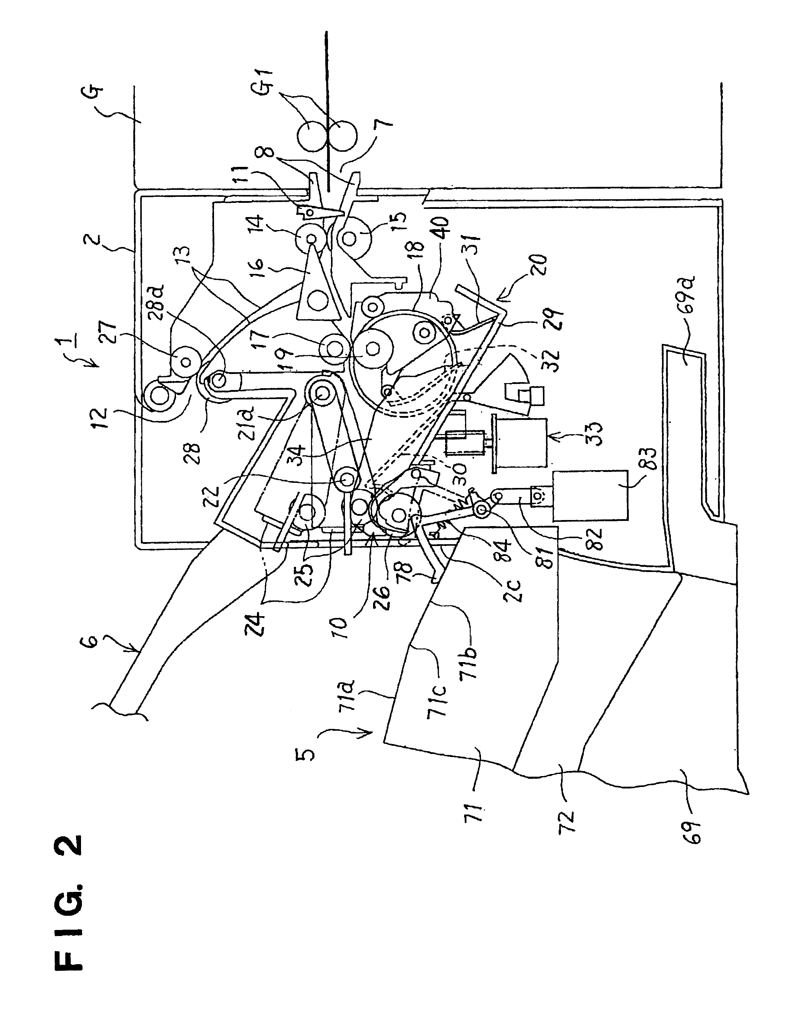
In FIG. 1, FIG. 2, and FIG. 3, a finishing apparatus 1 as a sheet receiving apparatus is disposed adjacent to an image forming apparatus G, such as a copy machine and a printing machine. In this case, it is desirable to detachably attach the finishing apparatus 1 to the apparatus G.

The finishing apparatus 1 is formed of a main apparatus 2; a staple unit 3 attached to one side frame 2a of the main apparatus 2; a driving transmission system 4 (refer to FIG. 9 and FIG. 10), described later, disposed in the other side frame 2b of the main apparatus 2; an inlet 7 into which image-formed sheet S ejected from the image forming apparatus G is supplied; an ejection port 10...


PUM

PropertyMeasurementUnit
angleaaaaaaaaaa
movementaaaaaaaaaa
thicknessaaaaaaaaaa

Abstract

A sheet receiving apparatus includes a sheet placing surface inclined such that the sheet is placed toward an upstream side of an ejecting direction of a sheet ejecting device, a sheet pressing device for pressing the sheet toward the second sheet placing surface, a driving device connected to the sheet pressing device for retreating the sheet pressing device from the sheet placing surface every time the sheet is ejected and moving the sheet pressing device back to the sheet placing surface, and a sheet detecting device located at the upstream side of the ejecting device for detecting the sheet and actuating the driving device. The sheet can be properly stacked and placed on the sheet placing surface.

Description

1. Field of Related ArtThe present invention relates to a sheet receiving apparatus used for stacking or temporarily placing sheets, on which images are formed, ejected from an image forming apparatus, such as a copier and printer.Particularly, the invention relates to a sheet receiving apparatus, in which sheets ejected sequentially are stacked or placed with good alignment, and a jam caused by collision between the stacked or placed sheet and a sheet ejected subsequently thereto is prevented, so that a stacking performance or placing performance is not deteriorated.2. Prior ArtsConventionally, an apparatus for accumulating and stacking sheets, on which images are formed in an image forming apparatus, such as a copier and printer, has been known. It is needless to say that the apparatus of this type can stack image-formed sheets in a relatively large amount, and also in the apparatus, right before stacking, the sheets ejected from the image forming apparatus are temporarily placed....

Claims


Application Information

Patent Timeline
Patent Type & Authority Patents(United States)
IPC IPC(8): B42C1/12B65H31/36B65H31/26B65H31/34
CPCB42C1/12B65H31/26B65H31/36B65H2301/163B65H2404/265B65H2511/414B65H2511/514B65H2701/1313B65H2220/01
Inventor SAITO, TAKASHISANMIYA, SHIGEYUKI
Owner NISCA KK
Why Eureka
Eureka Blog
Learn More