Coordinated position control system, coordinate position control method, and computer-readable storage medium containing a computer program for coordinate position controlling recorded thereon

Inactive Publication Date: 2002-06-25
MITSUBISHI ELECTRIC CORP +1
View PDF13 Cites 45 Cited by
  • Summary
  • Abstract
  • Description
  • Claims
  • Application Information

AI Technical Summary

Benefits of technology

The direction correcting section 11b is provided to reduce, when a movement vector substantially changes according to a change in illuminating conditions, the influence of this change over a cursor display and to realize a smooth cursor display.
As described above, in Embodiment 1, the direction computing section 11a computes a movement vector from an image captured up by the image sensor 10a, and when the computed movement vector is larger than a prespecified threshold value, the direction correcting section 11b determines the movement vector as invalid based on the recognition that the movement vector has acutely changed due to a change in the illuminating conditions or for some other reasons, so that offset of a cursor trajectory can be prevented with operability of a pointing device improved even when the illuminating conditions or other conditions change suddenly.

Problems solved by technology

However, when it is tried to update a cursor position by using a movement vector computed from an image photographed with an image sensor based on the conventional technology as described above, for instance, when the illuminating conditions change rapidly, sometimes a trajectory actually drawn by a cursor may be different from that intended by a user.
Further, when a user moves a pointing device extremely slowly, each component of a computed movement vector, which should be an integer number, may be a value less than 1, and consequently sometimes a cursor position is not correctly updated according to a movement vector and the cursor is disadvantageously stopped.
For the reasons as described above, how to efficiently solve such problems as offset of a cursor trajectory due to an abrupt change in illuminating conditions and stopping of a cursor position when moved very slowly, when updating a cursor position according to a movement vector computed from an image, are extremely important problems.

Method used


Image

  • Coordinated position control system, coordinate position control method, and computer-readable storage medium containing a computer program for coordinate position controlling recorded thereon
  • Coordinated position control system, coordinate position control method, and computer-readable storage medium containing a computer program for coordinate position controlling recorded thereon
  • Coordinated position control system, coordinate position control method, and computer-readable storage medium containing a computer program for coordinate position controlling recorded thereon

Examples


embodiment 2

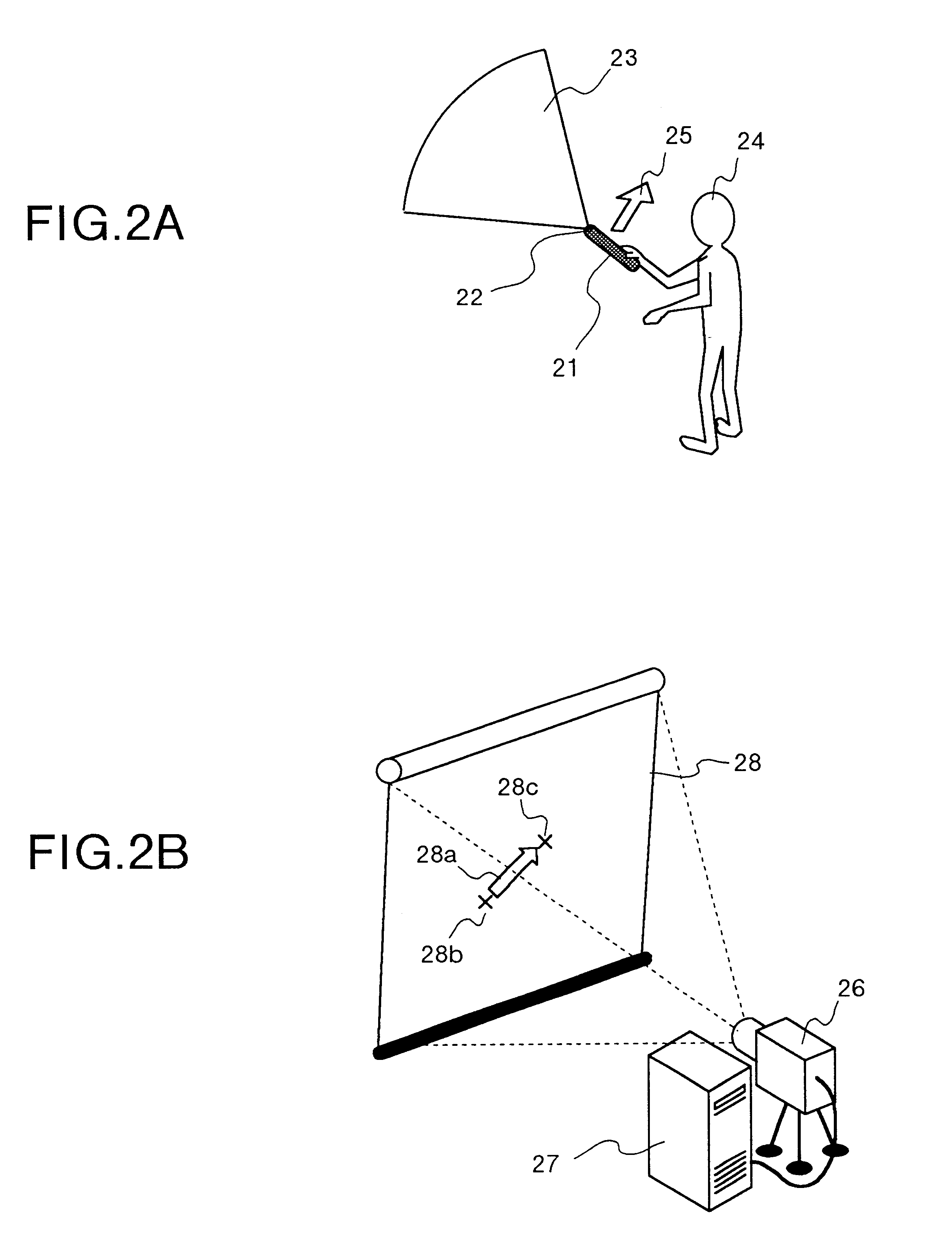
In Embodiment 2 of the present invention, when a user extremely slowly operates the pointing device 10, a cursor can smoothly be moved by accumulating small movement vectors successively computed from image data and updating a coordinate position according to the accumulated movement vectors.

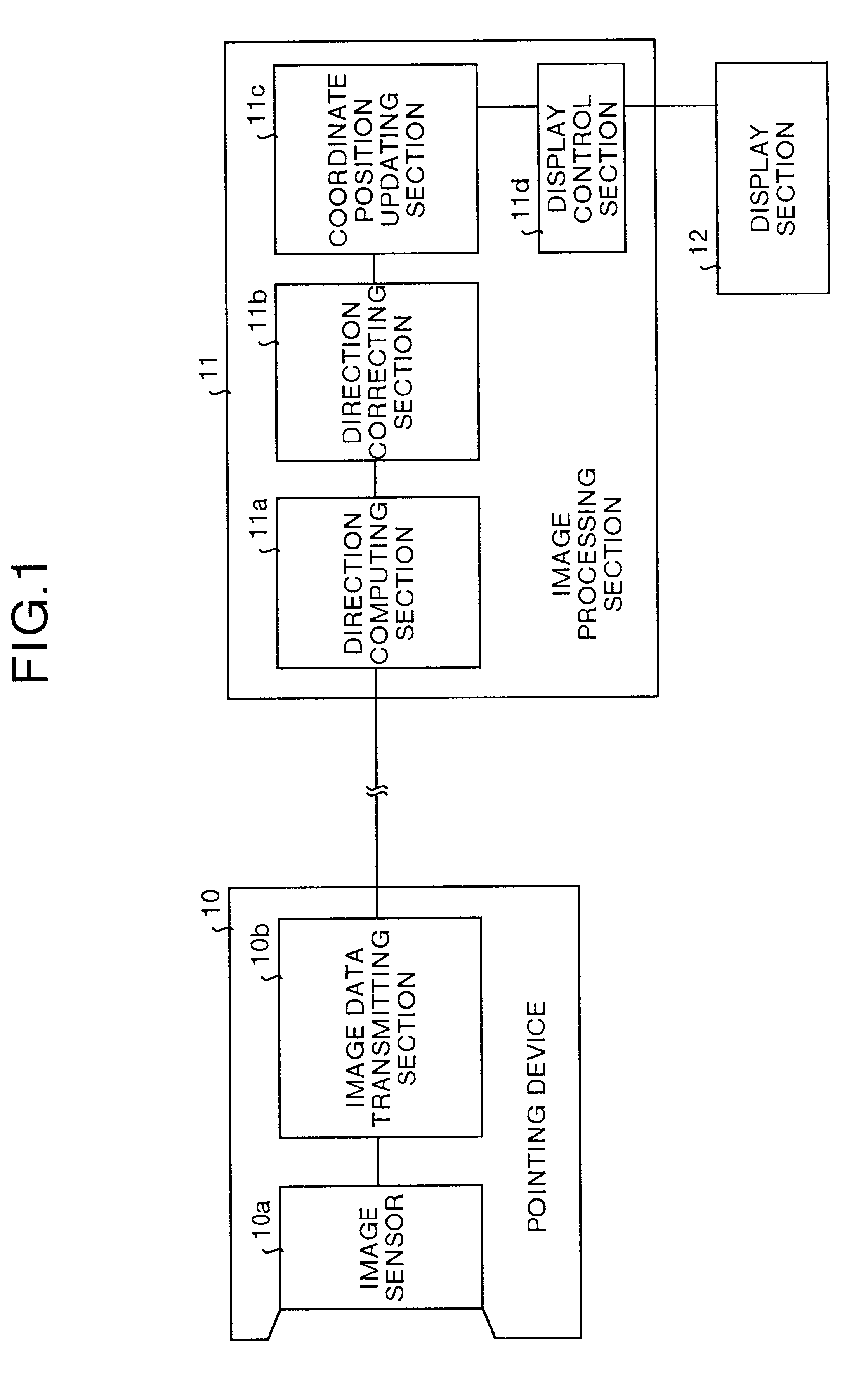
It should be noted that, also in Embodiment 2, the system configuration of the coordinate position control system is the same as that shown in FIG. 1 so that description thereof is omitted herein, and description is made centering on the processing for determining the validity by the direction correcting section 11.

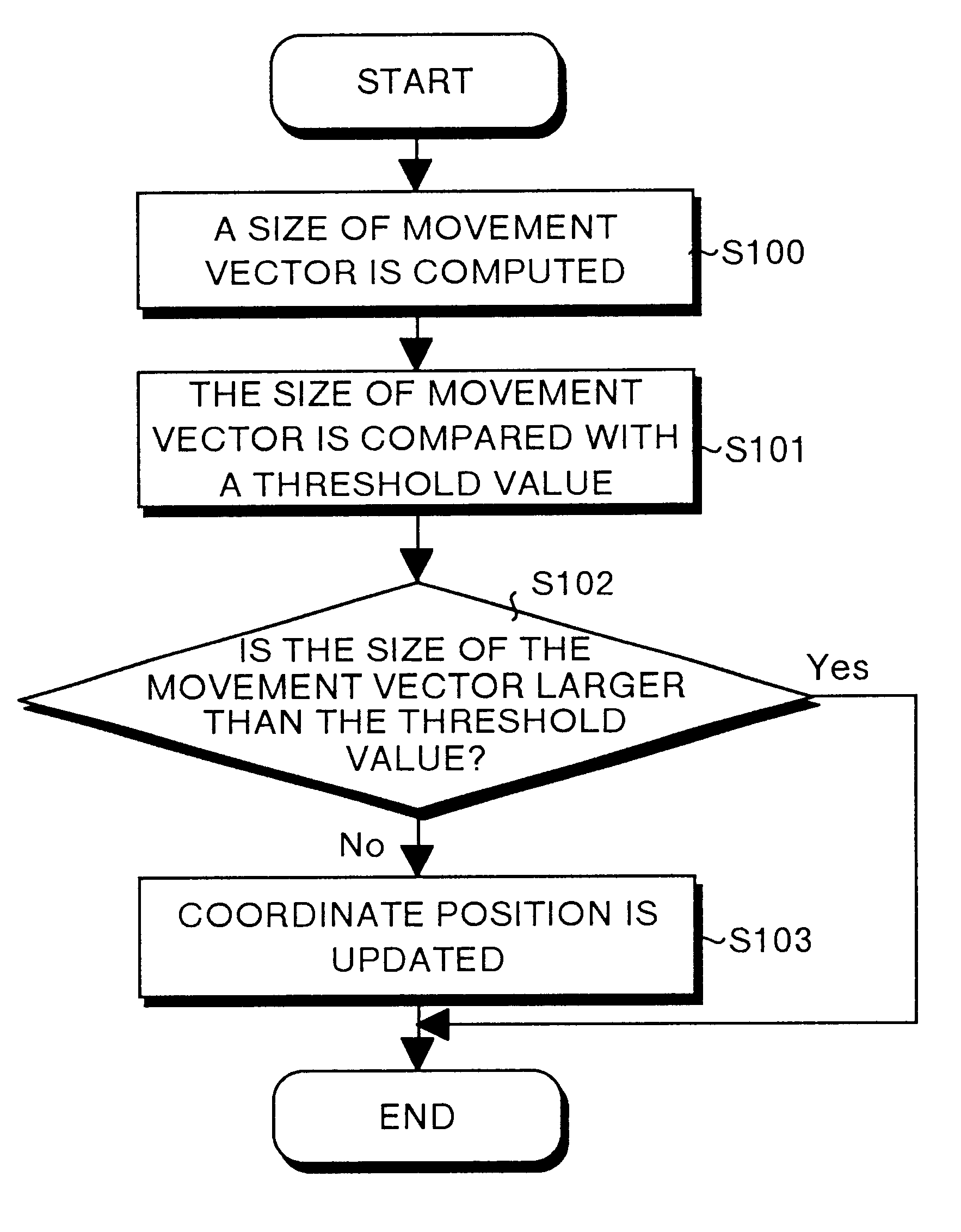
The direction correcting section 11b used in this embodiment executes the processing for comparing a size of a movement vector with a prespecified threshold value like in Embodiment 1 described above, and when the size of the movement vector is smaller than a prespecified threshold value, the direction correcting section 11b computes an accumulated vector by successively adding and st...


PUM


Abstract

When an operator operates a pointing device, a direction computing section computes a movement vector from an image photographed by an image sensor, and when the movement vector is larger than a threshold, a direction correcting section determines the movement vector as invalid based on the recognition that the movement vector was caused by an abrupt change in the illumination or other conditions, and outputs only movement vectors that are smaller than the threshold to a coordinate position updating section.

Description

The present invention relates to a coordination position control system for updating a coordinate position of a cursor or an icon displayed on a screen or a display unit from a movement vector computed using an image captured with an image sensor, a coordinate position control method, and a computer-readable storage medium containing a program for coordinate position controlling recorded thereon.A mouse has been widely used as a pointing device used in information terminal equipment such as a personal computer, and especially a mechanical mouse with a ball provided therein for two-dimensionally moving and controlling a mouse cursor in response to rotation of the ball is used most popularly.With the conventional type of mechanical mouse as described above, as a cursor can be moved only two-dimensionally, and to overcome this limitation, recently there has been developed and put into practical used the coordinate position control technology enabling three-dimensional movement of a cur...

Claims


Application Information

Patent Timeline
IPC IPC(8): G06F3/033G06F3/038G06F3/0346G06F3/041G06F3/042G06T7/20
CPCG06F3/0304
Inventor KAGE, HIROSHIFUNATSU, EIICHIAOYAGI, TETSUJISUZUKI, HAJIME
Owner MITSUBISHI ELECTRIC CORP
Why Eureka
Try Eureka