
Method and apparatus for controlling the flow of data frames through a network switch on a port-by-port basis

a network switch and data frame technology, applied in the field of communication systems, can solve the problems of reducing the overall efficiency of the system, affecting the speed of data frame flow, and increasing the latency of the queu

Inactive Publication Date: 2002-06-11
ADVANCED MICRO DEVICES INC
View PDF12 Cites 157 Cited by
  • Summary
  • Abstract
  • Description
  • Claims
  • Application Information

AI Technical Summary

Problems solved by technology

Without the use of buffers, there is a great likelihood that data frames will be lost, hence requiring retransmission and reducing the overall efficiency of the system.
The greater the capacity of the queue to store entries, the higher the latency of the queue.
During normal operation, however, there is always a possibility that the network will become congested.
Network congestion occurs if a receiving network element, for example a receiving network station, is unable to receive data at a rate that is greater than or equal to the transmission rate of the transmitting element.
If the number of client requests exceeds the capacity of the server's buffer, some of the data packets will be lost.
In another example, a client having limited buffer space may be unable to keep up with the transmission rate of a transmitting station, again resulting in lost packets.
Finally, network congestion may occur if a one or more transmitting stations attempt to transmit data packets, via the network switch, to a receiving station that is already in the process of receiving data packets from another transmitting station.
Hence, the receiving station may be unable to keep up with rece

Method used


Image

  • Method and apparatus for controlling the flow of data frames through a network switch on a port-by-port basis
  • Method and apparatus for controlling the flow of data frames through a network switch on a port-by-port basis
  • Method and apparatus for controlling the flow of data frames through a network switch on a port-by-port basis

Examples


Embodiment Construction

The present invention will be described with the example of a switch in a packet switched network, such as an Ethernet (IEEE 802.3) network. It will become apparent, however, that the present invention is also applicable to other packet switched systems, as described in detail below, as well as to other types of systems in general.

Switch Architecture Overview

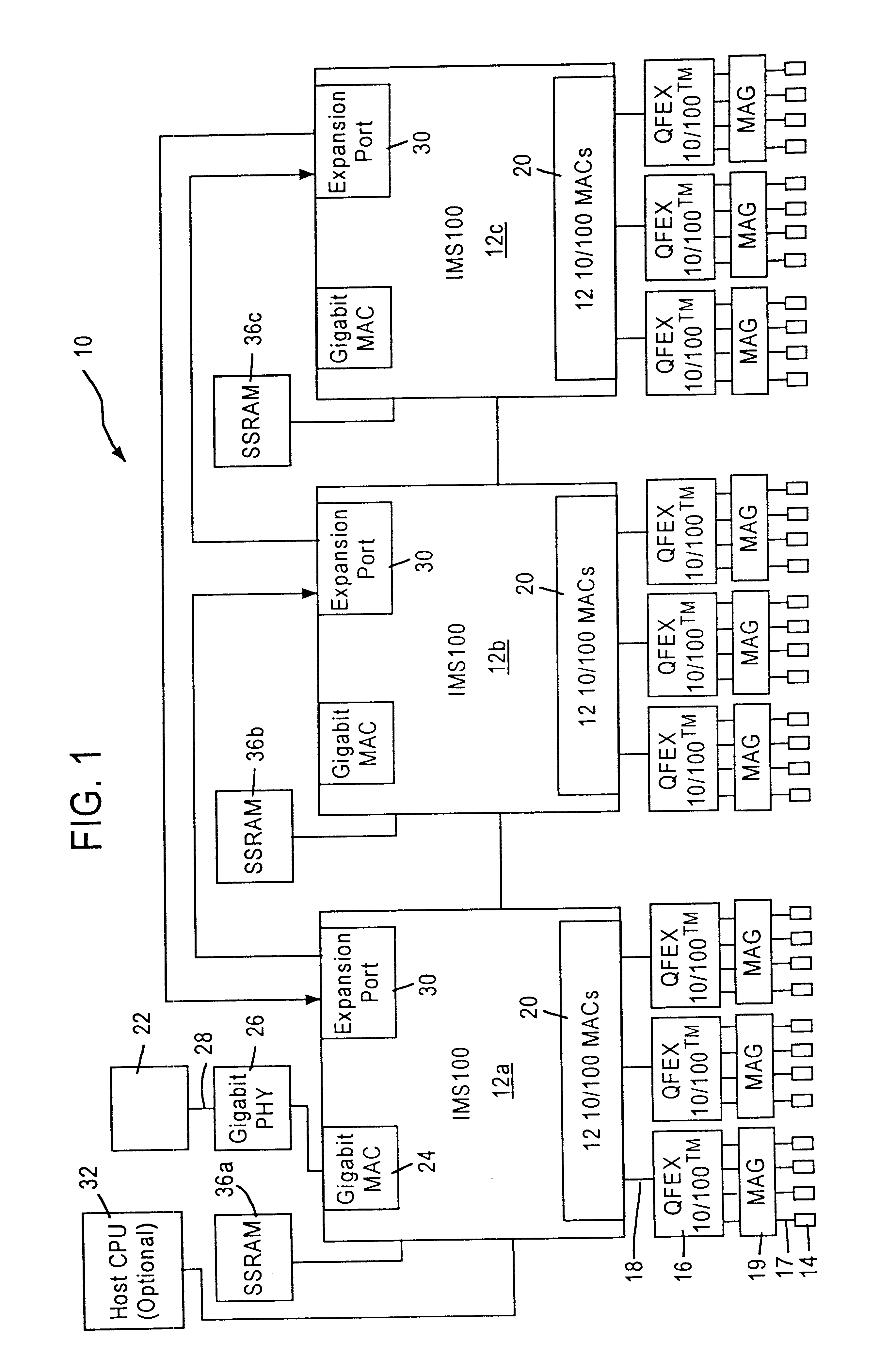
FIG. 1 is a block diagram of an exemplary system in which the present invention may be advantageously employed. The exemplary system 10 is a packet switched network, such as an Ethernet (IEEE 802.3) network. The packet switched network includes integrated multiport switches (IMS) 12 that enable communication of data packets between network stations. The network may include network stations having different configurations, for example twelve (12) 10 megabit per second (Mb / s) or 100 Mb / s network stations 14 (hereinafter 10 / 100 Mb / s) that send and receive data at a network data rate of 10 Mb / s or 100 Mb / s, and a 1000 Mb / s (i.e., 1 ...


PUM


Abstract

An apparatus and method are disclosed for regulating the flow of data between plural network stations through a network switch. A receive port functions to receive data frames from a first network station, and a transmit port outputs the received data frames to a second network station. A programmable threshold register is provided for storing a threshold value that indicates a saturation level for the internal resources of the transmit port. Control circuitry is used to monitor the internal resources of the transmit port and determine whether or not the threshold value has been reached. If the threshold value has been reached, then the control circuitry will implement a flow control process that causes the first network station to discontinue transmission of data frames to the transmit port until the internal resources of the transmit port fall below the threshold value.

Description

1. Field of the InventionThe present invention relates to communication systems, and more particularly, to a method and apparatus for selectively controlling the flow of data between plural network stations.2. Description of the Related ArtModem communication systems, such as computer networking systems or communication networks, provide constant transmission of data between end stations and / or intermediate stations such as routers and signal amplifiers. Computer networking systems, such as packet switched networks (e.g., Ethernet networks), often require transmission of data to a single end station or to multiple end stations within the network. The data originates from a user program, and is segmented into multiple data frames and subsequently transmitted in order to simplify processing and minimize the retransmission time required for error recovery. For example, in a conventional e-mail system, a user may desire to send the same e-mail message to four different users that are co...

Claims


Application Information

Patent Timeline
IPC IPC(8): H04L12/56H04L29/06
CPCH04L29/06H04L47/10H04L47/266H04L49/901H04L47/30H04L49/90H04L47/29H04L9/40
Inventor ERIMLI, BAHADIRWILLIAMS, ROBERTMERCHANT, SHASHANK
Owner ADVANCED MICRO DEVICES INC
Learn More