
Method and apparatus for cooling electronic components

a technology for electronic components and cooling methods, applied in the field of heat transfer, can solve problems such as chip malfunction, chip heat generation, and common cooling methods that are mentioned above, and achieve the effect of improving the cooling effect of high-performance electronic systems

Inactive Publication Date: 2002-06-04
ORACLE INT CORP
View PDF11 Cites 120 Cited by
  • Summary
  • Abstract
  • Description
  • Claims
  • Application Information

AI Technical Summary

Problems solved by technology

When in use, the chips often produce significant levels of heat.
The increased level of heat produced by these chips can lead to a number of problems, for example, elevated levels of heat can potentially cause the chip to malfunction.
The commonly used methods of cooling that are mentioned above have sometimes been found to be inadequate for cooling high performance electronic systems.
As the package sizes for electronic systems get smaller, the more difficult it becomes to provide and direct an adequate airflow to the various heat sources and through the system.

Method used


Image

  • Method and apparatus for cooling electronic components
  • Method and apparatus for cooling electronic components
  • Method and apparatus for cooling electronic components

Examples


Embodiment Construction

Illustrative embodiments of the invention are described below. In the interest of clarity, not all features of an actual implementation are described in this specification. It will of course be appreciated that in the development of any such actual embodiment, numerous implementation-specific decisions must be made to achieve the developers' specific goals, such as compliance with system-related and business-related constraints, which will vary from one implementation to another. Moreover, it will be appreciated that such a development effort might be complex and time-consuming, but would nevertheless be a routine undertaking for those of ordinary skill in the art having the benefit of this disclosure.

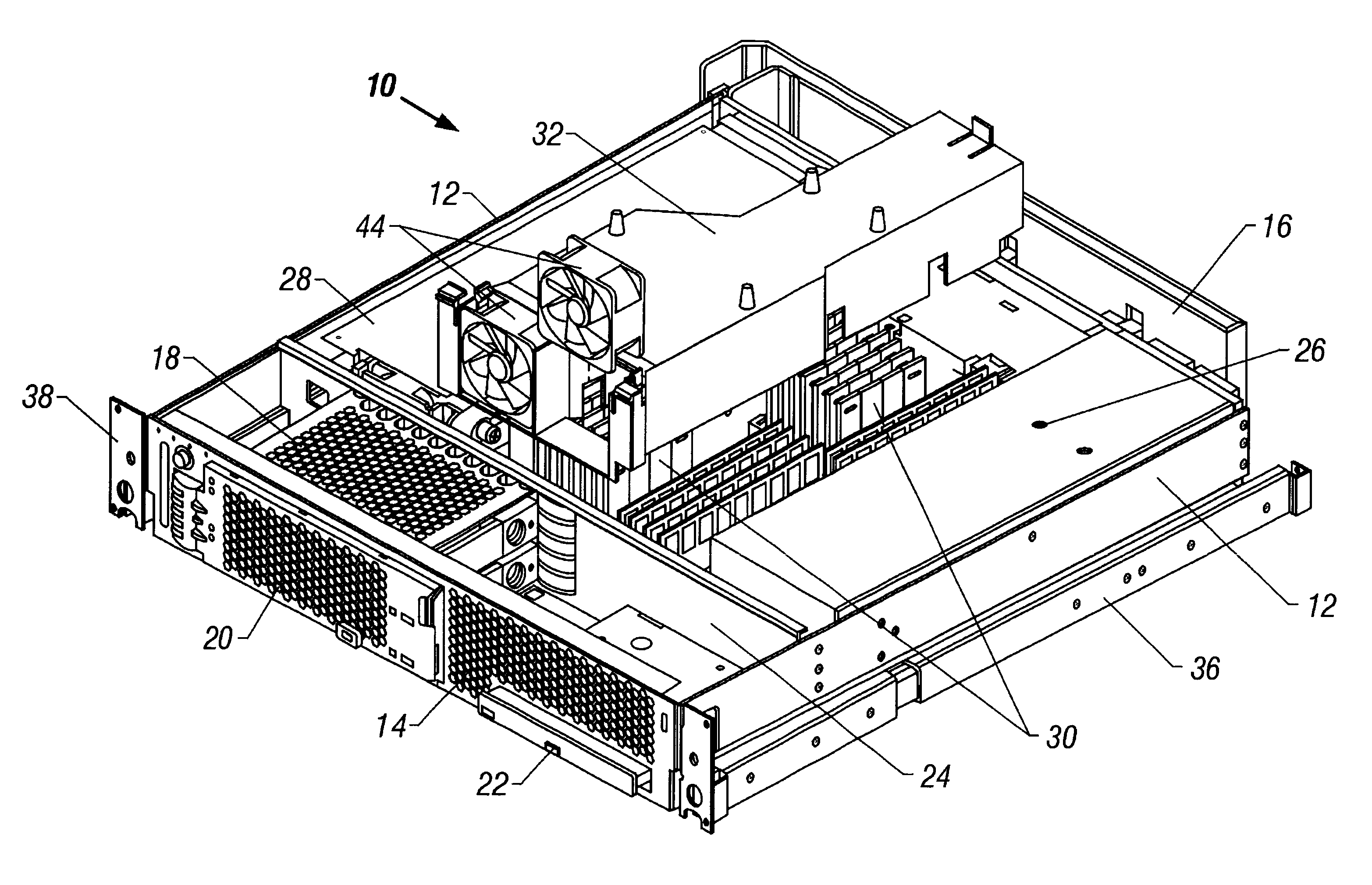
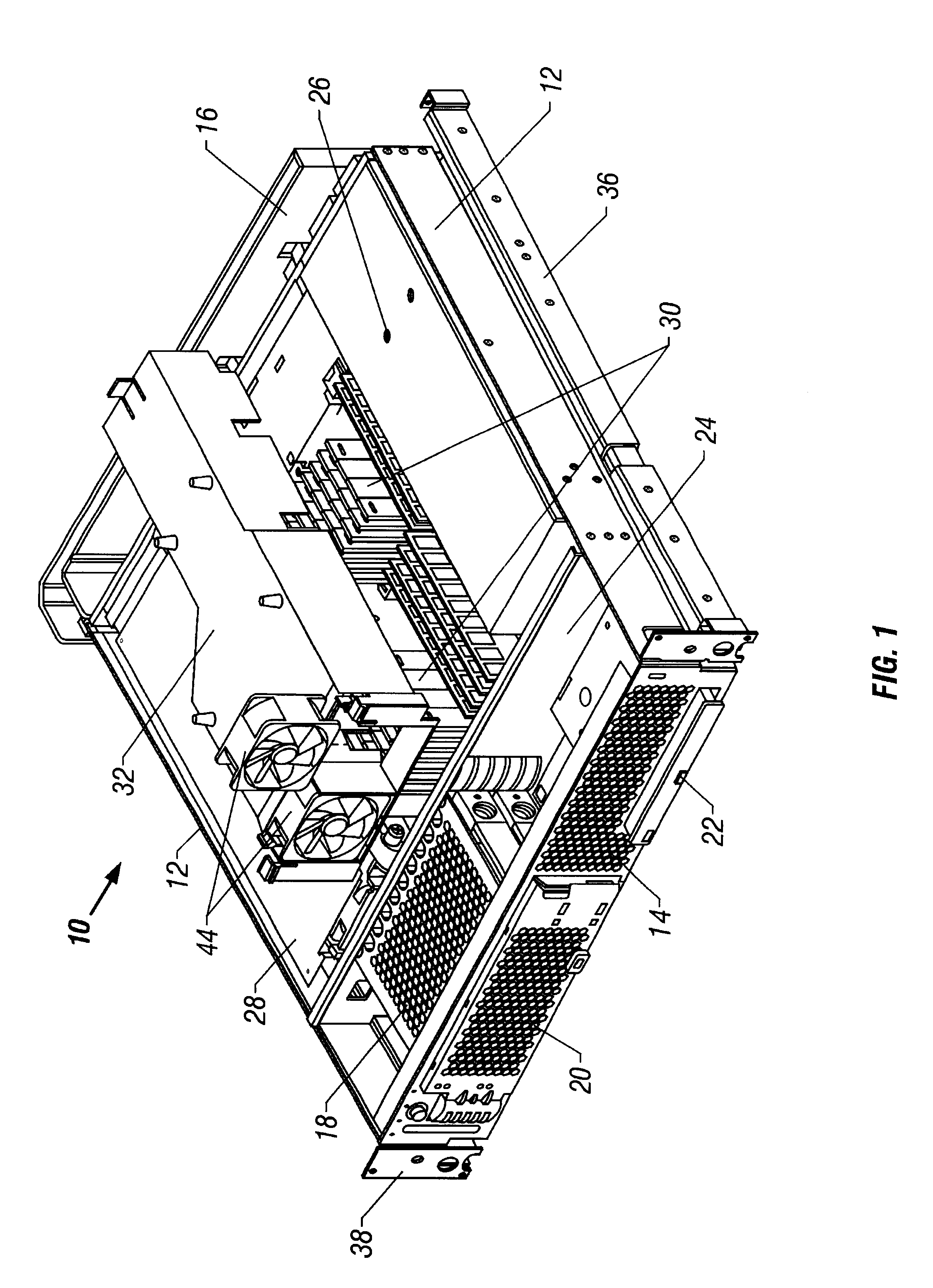
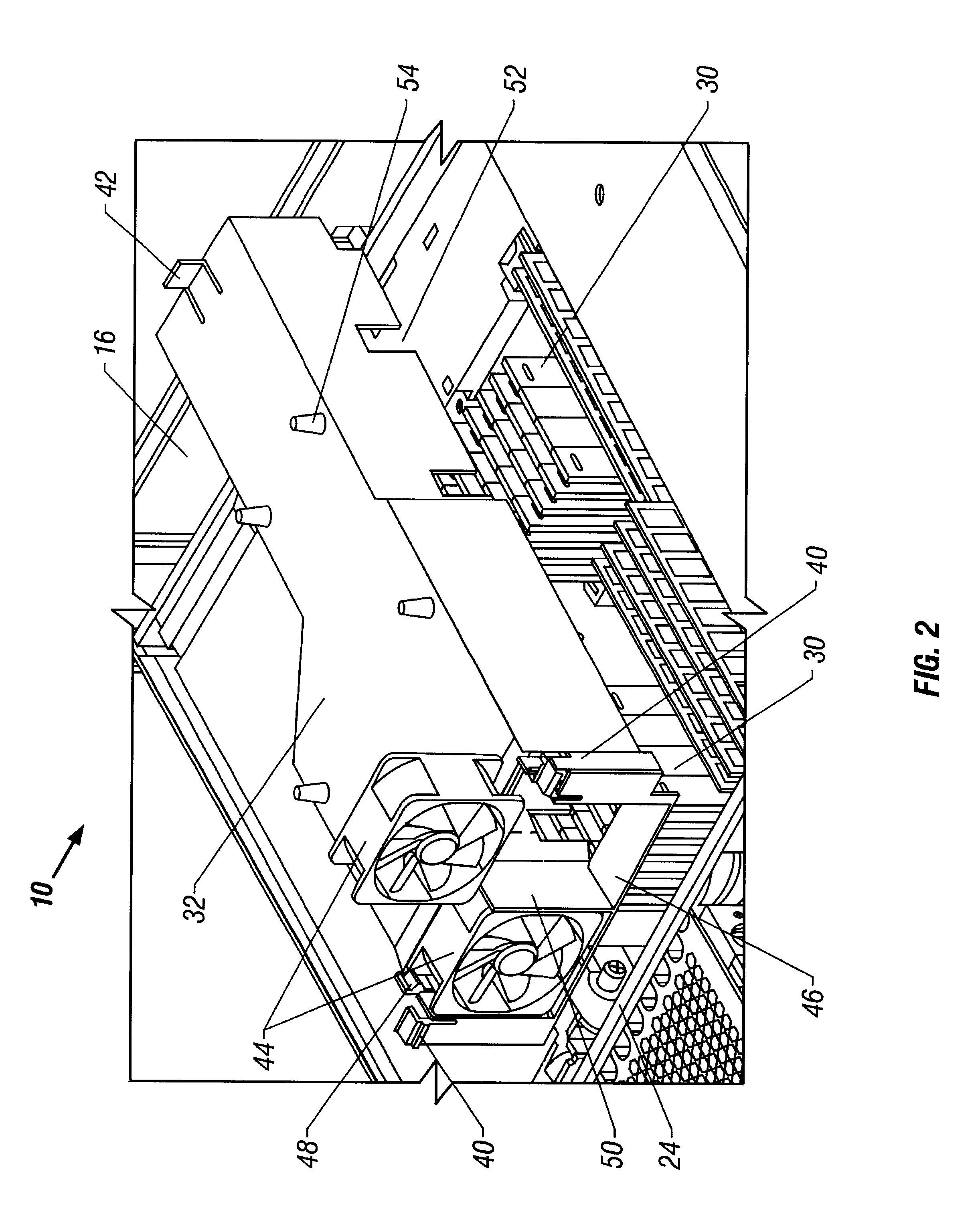
Referring to the attached drawings, FIG. 1 shows a partially exploded top perspective view of the interior of a computer assembly 10 comprising a chassis 12 with a front enclosure 14 and a rear enclosure 16. A removable device compartment 18 is shown having two hard disk drives 20 and ...


PUM


Abstract

The present invention discloses improved cooling designs and methods for the cooling of heat sources. One embodiment of the present invention is a cooling system comprising a housing and at least one divider disposed within the housing. The at least one divider creates a plurality of airflow channels through the housing. Another embodiment of the invention is a method for dissipating heat from heat sources within an electrical assembly comprising at least partially separating the heat sources with a divider. Separate airflow channels are created whereby the separated heat sources are disposed within the separated airflow channels. Forced airflow streams are generated through the separated airflow channels, thereby dissipating heat from the heat sources into the forced airflow streams.

Description

1. Field of the InventionThis invention relates generally to heat transfer, and, more particularly, to cooling assemblies and methods to remove at least some of the heat produced by a heat source, such as an electronic component.2. Description of Related ArtElectronic components such as integrated circuits or semiconductor chips, hereafter referred to as "chips", are well known and commonly used in the art to perform electronic functions. When in use, the chips often produce significant levels of heat. To reduce the heat generated, the chip size needs to be decreased, which causes the heat to be concentrated into a smaller area. As technology has increased the capacity of the chips to perform functions, it has been found that the amount of concentrated heat produced has increased significantly. The increased level of heat produced by these chips can lead to a number of problems, for example, elevated levels of heat can potentially cause the chip to malfunction.Various methods have b...

Claims


Application Information

Patent Timeline
Patent Type & Authority Patents(United States)
IPC IPC(8): G06F1/20H05K7/20
CPCG06F1/20
Inventor KIM, DAVID K. J.RUCKMAN, WILLIAM W.STRUVE, DIMITRY
Owner ORACLE INT CORP
Learn More