Eureka AIR delivers breakthrough ideas for toughest innovation challenges, trusted by R&D personnel around the world.

Internal combustion engine with fuel injection

a fuel injection and combustion engine technology, applied in the direction of machines/engines, mechanical equipment, cylinders, etc., can solve the problems of affecting the discharge of nitrogen oxides, the combustion process is very complicated, and the inability to commence fuel injection too early,

Inactive Publication Date: 2002-05-07
SCANIA CV AB
View PDF7 Cites 16 Cited by
  • Summary
  • Abstract
  • Description
  • Claims
  • Application Information

AI Technical Summary

Benefits of technology

The object of the invention is to provide a solution which brings about relatively late injection of the fuel so that the engine will not emit large amounts of nitrogen oxides, while at the same time the injection will not cause soot formation with its attendant disadvantages.
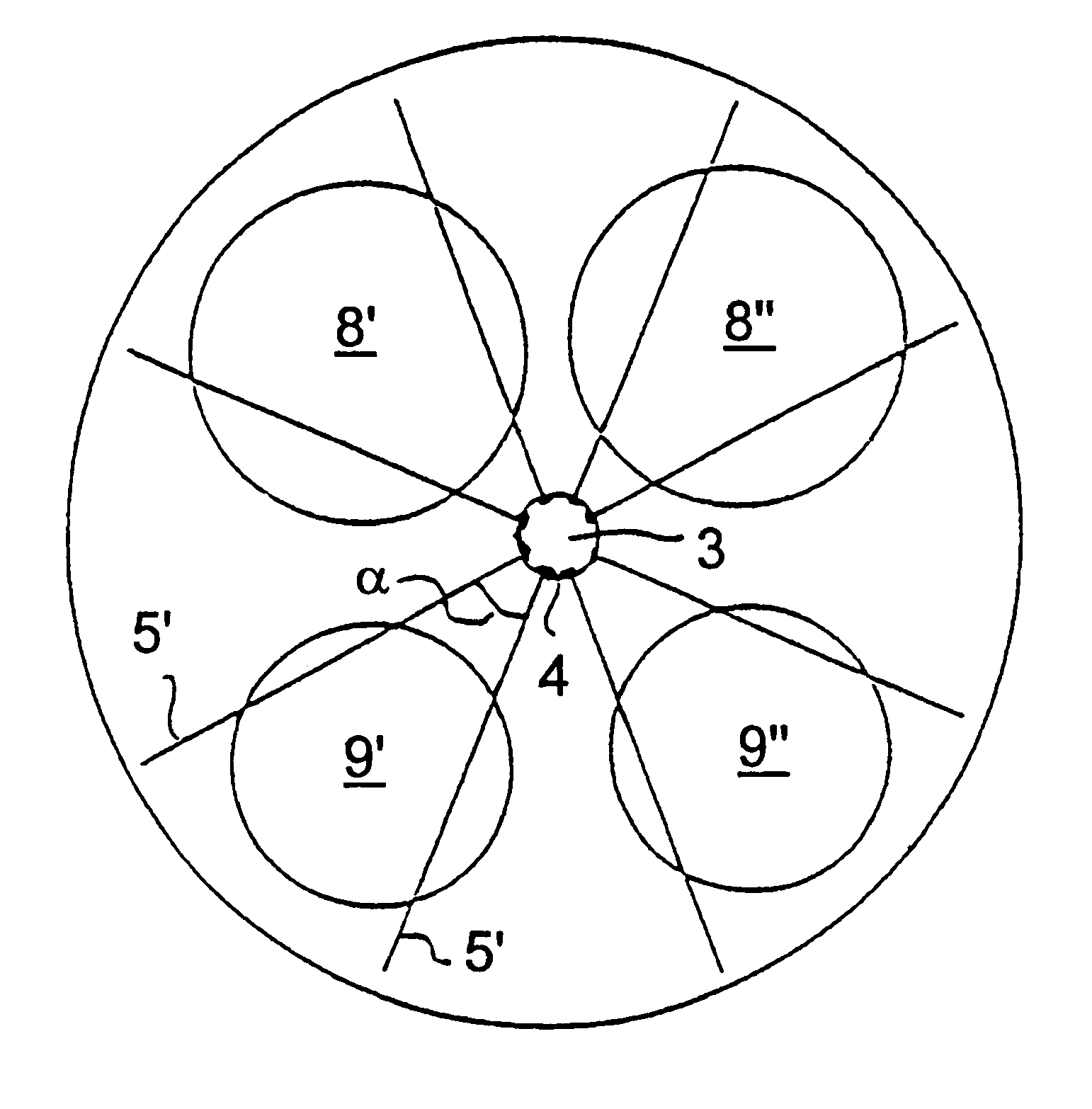
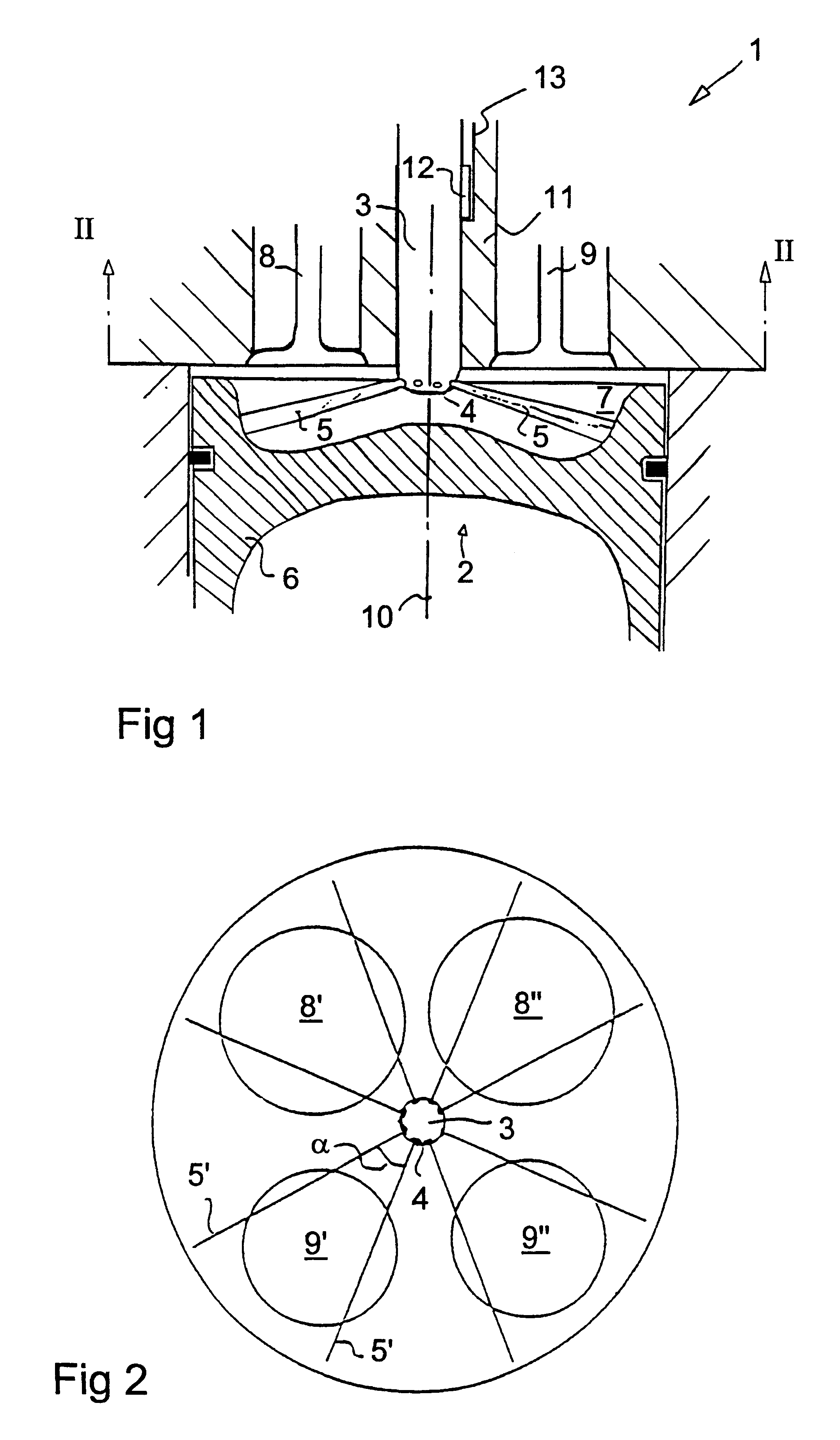
The object of the invention is achieved by the fuel injector nozzle being so oriented in the cylinder that the projection of each fuel spray injection, viewed in a plane perpendicular to the cylinder center line, crosses a projection in the same plane of the valve disc of one of the valves. Orienting the fuel injector in this manner will cause the fuel spray to pass under a valve. Thermal radiation from the valve will cause more effective combustion and keep soot formation at a low level. As all the fuel sprays will be affected by valve heat, a more uniform environment for the various fuel sprays is achieved, resulting in a more homogeneous combustion. This is further assisted by the fact that a larger proportion of the fuel comes close to the hot valves. It will thus be possible to effect injection even at a time when the piston is relatively far from the injector and there would otherwise be risk of the fuel sprays reaching the cylinder wall.

Problems solved by technology

A major problem in this connection is that the combustion process is very complicated, so a measure adopted for a particular purpose often entails unintended disadvantages in another domain.
With regard to emission of nitrogen oxides it is undesirable to commence fuel injection too early.
Nor is it desirable to increase the injection pressure overmuch, since this also adversely affects discharges of nitrogen oxides.
On the other hand, it is undesirable to cease injection too late, since this increases the occurrence of undesirable residues of more or less unburnt fuel which may result in a variety of problems.
As the cylinder walls are significantly cooler than the temperature in the piston hollow, this causes the occurrence of uncombusted particles usually known collectively as soot.
This worsens the oil's lubricating characteristics, thereby possibly resulting in serious wear damage to the engine.
All these measures entail solutions which are complicated, space-consuming and expensive.
The foregoing shows that there is a problem in that the period of time available for injection is too limited.
It is therefore difficult to effect fuel injection in such a way as to meet all the requirements and, in particular, to do so in such a way as to achieve both low emissions of nitrogen oxides and little soot formation.
This means, however, that at the commencement of injection the piston is too near to the injector and there is too little space between the injector and the piston for the fuel to become finely distributed before it reaches the piston.
Such a solution would entail, however, exacting requirements with regard to injector control and result in an expensive and complicated solution.
Despite in that case a smaller amount of fuel being directed between the valves, this means that these sprays will reach the cylinder wall if injection takes place late, with the result that the aforesaid soot formation problem persists.

Method used


Image

  • Internal combustion engine with fuel injection
  • Internal combustion engine with fuel injection

Examples


Embodiment Construction

FIG. 1 depicts a four-stroke four-cylinder combustion engine 1, and more specifically a piston engine in the form of a diesel engine intended to drive a heavy-duty vehicle such as a truck or a bus. FIG. 1 shows only one cylinder 2, since all the cylinders are identical in form. The combustion engine 1 is provided with direct injection and has for this purpose in each cylinder a fuel injector 3 which, via a number of fuel nozzles 4, can deliver fuel sprays 5 in various directions in the cylinder 2. These fuel sprays 5 are in a conventional manner directed somewhat downwards along the shell surface in a conical shape. When a piston 6 in the cylinder is in an upper position, these fuel sprays 5 are directed into a recess 7 at the top of the piston 6. The cylinder 2 contains not only the piston 6 and the fuel injector 3 but also a number of valves 8,9 in the form of disc valves between which the fuel injector 3 is arranged, advantageously centrally. At least one valve 8 constitutes an i...


PUM


Abstract

A combustion engine with direct injection has in each cylinder a fuel injector (3) whose fuel orifices (4) are so oriented that the projection (5') of the direction of each fuel spray, viewed in a plane perpendicular to the cylinder centerline, crosses a projection (8', 8'', 9', 9'') in the same plane of the valve disc of one of the valves.

Description

TECHNICAL DOMAINThe present invention relates to an internal combustion engine with direct fuel injection, preferably a diesel engine, and concerns as an arrangement of the fuel injection nozzles to direct fuel spray past the valves for the cylinder.STATE OF THE ARTWithin vehicle engine technology there is ever greater demand for increased performance while at the same time increased environmental requirements are being set for emissions from engines. A major problem in this connection is that the combustion process is very complicated, so a measure adopted for a particular purpose often entails unintended disadvantages in another domain.In direct injected diesel engines it has been necessary to compromise on various parameters in order to achieve acceptable combinations of performance and environmental acceptability. With regard to emission of nitrogen oxides it is undesirable to commence fuel injection too early. Nor is it desirable to increase the injection pressure overmuch, sin...

Claims


Application Information

Patent Timeline
IPC IPC(8): F02M61/18F02M61/00F02M61/14F02B23/02F02B23/06F02F3/26F02F1/42F02F1/24F02B3/06F02B3/00
CPCF02B23/0669F02B23/0696F02F1/4214F02M61/14F02M61/1806F02F3/26F02B3/06F02B2275/14Y02T10/123F02F2001/247Y02T10/125Y02T10/12
Inventor HANSSON, LEIF
Owner SCANIA CV AB
Why Eureka
Eureka Blog
Learn More