Tube-pressed brake
a technology of brakes and tubes, applied in drum brakes, mechanical equipment, coatings, etc., can solve the problems of insufficient satisfaction of conventional tubes, which use rubber or the like as they are, and achieve the effect of improving the service life and improving the service life of tubes
- Summary
- Abstract
- Description
- Claims
- Application Information
AI Technical Summary
Benefits of technology
Problems solved by technology
Method used
Image

Examples
first embodiment
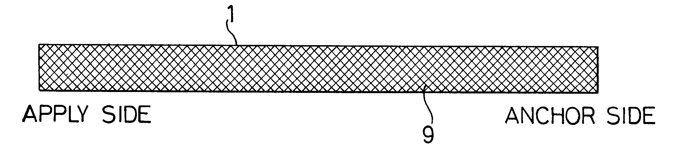
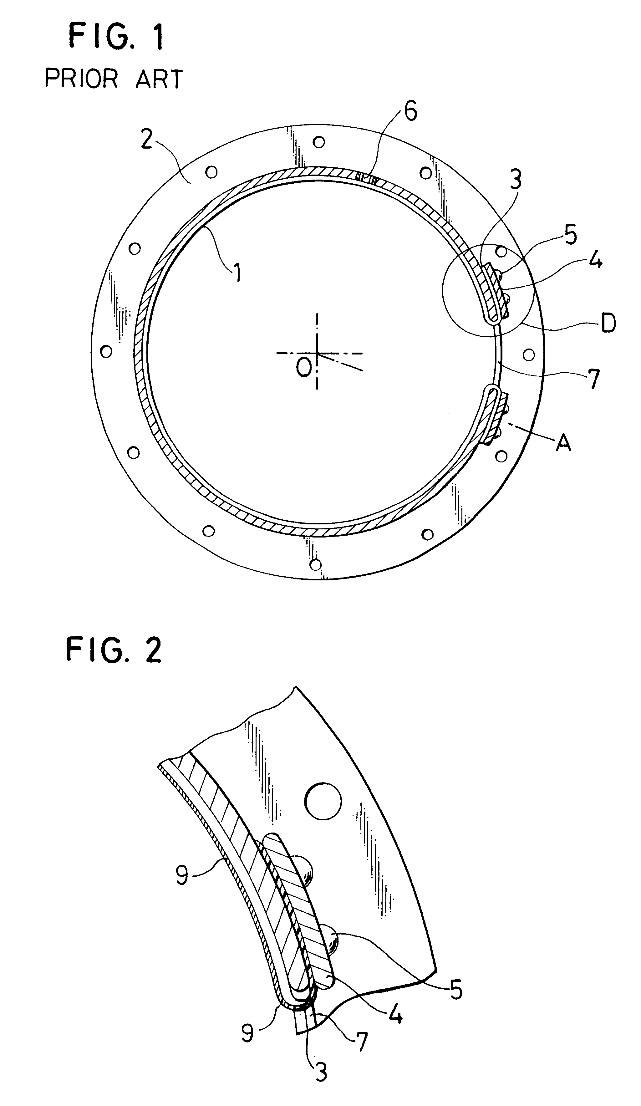
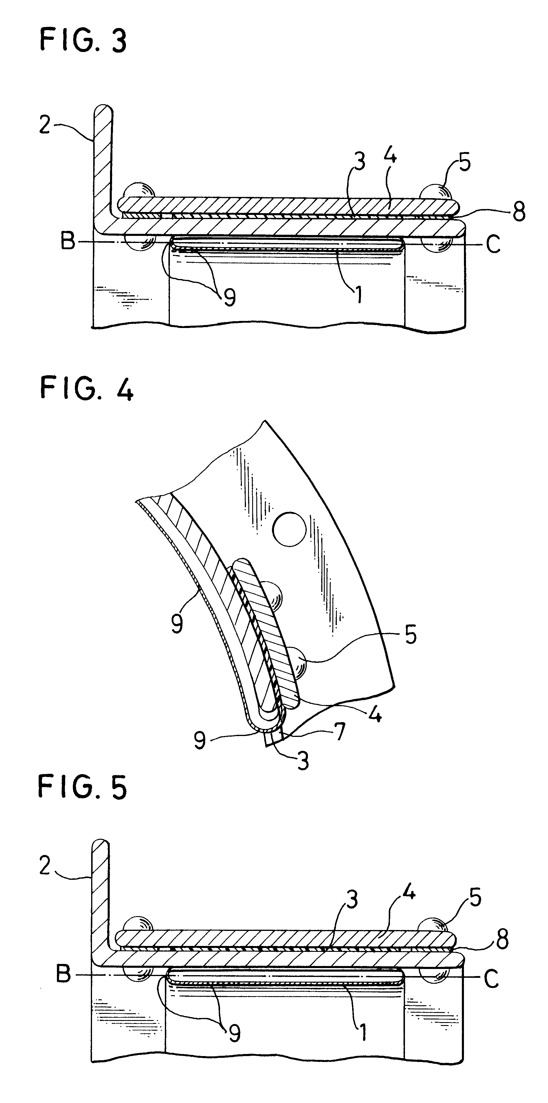
the present invention will be described first with reference to FIGS. 2 and 3, in which like reference numerals as in FIG. 1 indicate like elements of structure. In FIG. 3, numeral 8 indicates a spacer arranged between the outer frame 2 and the presser plate 4. In the first embodiment, a tube 1 is applied on an inner wall thereof with a coating 9. The term "inner wall" as used herein means a wall of the tube where the tube is brought into contact with a pressure fluid.
When a torque of a counterpart member (not shown) arranged on an inner side of the tube is transmitted to the tube upon actuation of the brake, the coating 9 reinforces the folded portion 3 on which a load concentrates. Further, the coating 9 can prevent the tube 1 from failing to retain its shape when the pressure fluid is drawn out of the tube 1 to release the brake, and during idling, the coating 9 can prevent the tube 1 from coming into contact with the counterpart member, thereby making it possible to avoid occurr...
third embodiment
With reference to FIG. 25 and FIG. 26, the present invention will now be described. In these drawings, like reference numerals as in FIG. 1 indicate like elements of structure. A tube 1 repeats expansion and contraction, so that fatigue accumulates at side portions. The tube 1 therefore unavoidably becomes weak at the side portions thereof. To cope with this problem, meshes may be incorporated as reinforcements in such side portions. A pressure fluid, however, tends to leak out through the mesh-reinforced side portions. This problem can be solved by applying coatings to the side portions of the tube as illustrated in FIG. 3.
fourth embodiment
Referring next to FIG. 27 and FIG. 28, the present invention will be described.
In these drawings, like reference numerals as in FIG. 1 indicate like elements of structure. Where a tube 1 itself has good friction characteristics and is also resistant to wearing, application of a coating to its frictionally engaging surface may conversely deteriorate the friction characteristics. According to the fourth embodiment, a coating is therefore applied at locations other than the frictionally engaging surface. Owing to the coating so applied, the tube 1 can retain its shape during a release of the tube-pressed brake, the side portions of the tube 1 can be prevented from oil leakage and can also be reinforced, and the frictional performance of the tube 1 itself can be fully utilized.
Depending on the kind of the coating material or in the case of a coating like that depicted in FIG. 27, the tube cannot retain its shape when a pressure is drawn out of the tube as in the case of the release of t...
PUM
| Property | Measurement | Unit |
|---|---|---|
| pressure | aaaaa | aaaaa |
| friction | aaaaa | aaaaa |
| heat resistance | aaaaa | aaaaa |
Abstract
Description
Claims
Application Information
 - R&D
- Intellectual Property
- Life Sciences
- Materials
- Tech Scout
- Unparalleled Data Quality
- Higher Quality Content
- 60% Fewer Hallucinations
Browse by: Latest US Patents, China's latest patents, Technical Efficacy Thesaurus, Application Domain, Technology Topic, Popular Technical Reports.
© 2025 PatSnap. All rights reserved.Legal|Privacy policy|Modern Slavery Act Transparency Statement|Sitemap|About US| Contact US: help@patsnap.com