
Vibration damping device

a damping device and vibration technology, applied in mechanical control devices, controlling members, controlled members, etc., can solve the problems of increasing the risk, reducing the pressure of individual deflection masses against the deflection path, and contact pressing forces generated by centrifugal for

Inactive Publication Date: 2002-04-23
MANNESMANN SACHS AG
View PDF20 Cites 22 Cited by
  • Summary
  • Abstract
  • Description
  • Claims
  • Application Information

AI Technical Summary

Benefits of technology

Accordingly, appropriate steps are taken in the vibration damping device according to the invention to compel the rolling movement of the at least one deflection mass and thereby prevent the transition to a state of sliding motion. Throughout the length of the deflection path and especially in the area of the respective ends of the deflection paths and when sharp changes in rotational speed occur, the at least one deflection mass moves along the associated deflection path while carrying out a rolling movement so that a defined proportion of the excitation energy is changed into rotational energy in these movement states or path areas. The detuning of the natural frequency occurring in the prior art due to undefined movement behavior is therefore prevented.
A further improved guiding action in the introduction of the positive rolling movement may be achieved when the guide projection / guide path arrangement comprises two groups of guide projections and guide paths associated with the latter and when one of the groups of guide projections with associated guide paths is provided at every axial end side of the at least one deflection mass with respect to the rolling axis of the same.
To prevent unwanted tilting of the at least one deflection mass in a construction of the type mentioned above, the rolling strip arrangement may comprise at least three rolling strip portions, wherein rolling strip portions which directly follow one another surround the deflection mass in opposite circumferential directions.

Problems solved by technology

However, when the deflection masses approach the end of the deflection path, the contact pressing forces which are generated by the centrifugal force and by which the individual deflection masses are pressed against the deflection paths decrease because of the increasing curvature of the paths.
The decrease in the contact pressing forces changes the friction ratios in the area of contact of the deflection masses at the associated deflection paths, thereby increasing the risk, especially in the end area of the individual paths, that a transition from a rolling movement to a sliding movement will occur and place the natural frequency of the oscillators out of tune.
The detuning of the natural frequency results in the loss of the adjustment to the frequency to be damped and the vibration damping device no longer fulfills its function in a satisfactory manner.

Method used


Image

  • Vibration damping device
  • Vibration damping device
  • Vibration damping device

Examples


Embodiment Construction

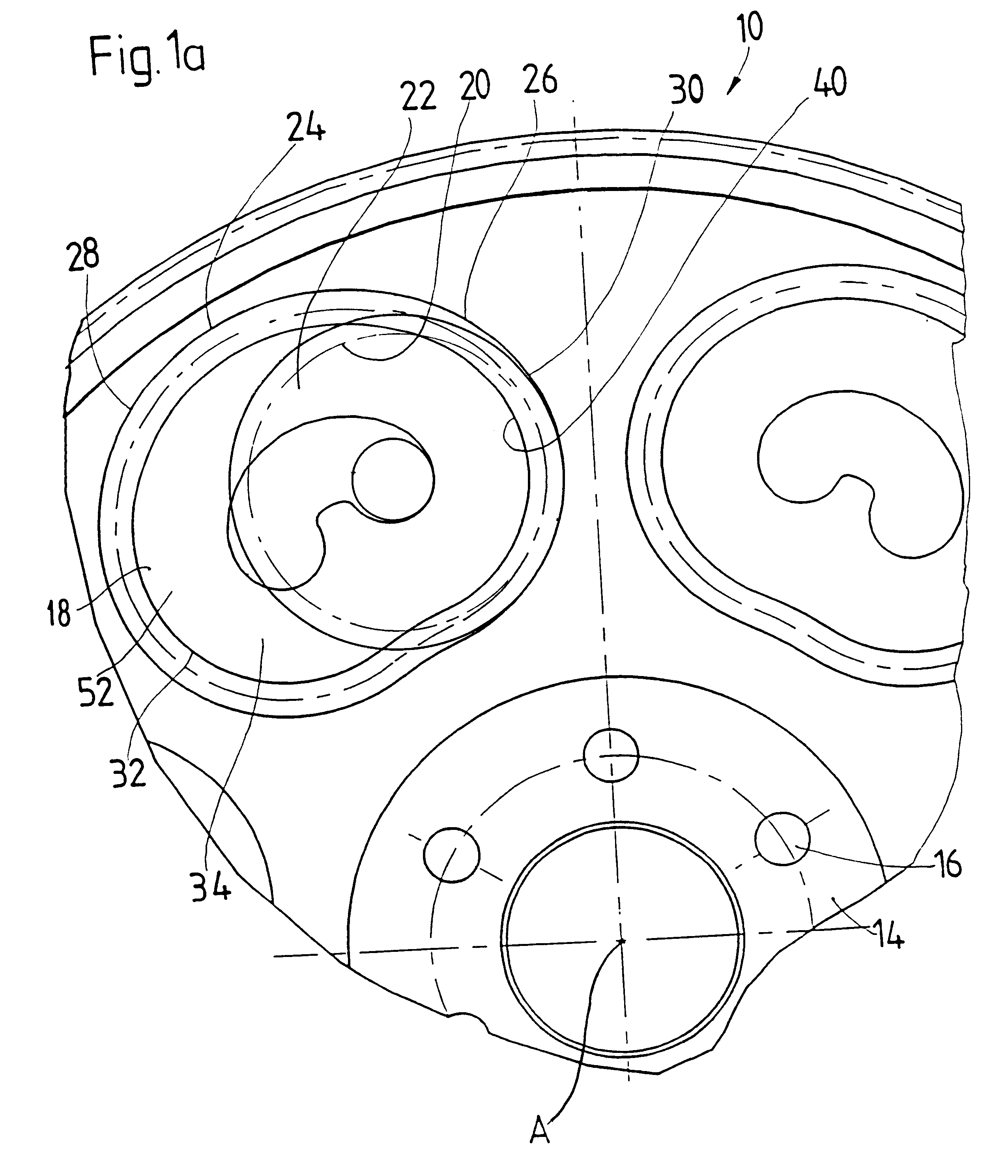
FIGS. 1 and 2 show a first embodiment form of a vibration damping device 10 constructed, for example, as a flywheel for a motor vehicle clutch. The vibration damping device 10 may alternatively be constructed as a flywheel mass of a multiple-mass flywheel or may be incorporated in any area as a separate flywheel arrangement in a rotating system. A base body 12 of the vibration damping device 10 extends around an axis of rotation A and is rotatable around this axis of rotation A. A radial inner side of the base body 12 has a shoulder area 14 with a plurality of screw openings 16 through which fastening pins may be guided, for example, for screwing the base body 12 onto a driveshaft or crankshaft of an internal combustion engine. A plurality of recesses 18 are distributed in the circumferential direction in the radial outer area of the base body 12. The recesses 18 are approximately kidney-shaped or peanut-shaped when viewed along the axial direction (see FIG. 1). A radial outer area ...


PUM


Abstract

A vibration damping device for a drive system of a motor vehicle, includes a deflection mass arrangement arranged in a base body which is rotatable about an axis of rotation (A). The deflection mass arrangement includes at least one deflection mass and a deflection path associated with the at least one deflection mass and along which the deflection mass moves during rotation of the base body about the axis of rotation (A). The deflection path has a vertex area and deflection areas on both sides of the vertex area. The deflection areas have a decreasing distance from the axis of rotation (A) as they proceed from the vertex area toward their circumferential end areas. A positive rolling arrangement is arranged between the at least one deflection mass and the deflection path which generates a rolling movement of the at least one deflection mass during the movement of the at least one deflection mass along the associated deflection path and thereby prevents a sliding movement of the deflection mass.

Description

1. Field of the InventionThe present invention relates to a vibration damping device for a drive system of a motor vehicle comprising a base body rotatable about an axis of rotation and a deflection mass arrangement arranged in the base body and having at least one deflection mass and a deflection path which is associated with the at least one deflection mass and along which the deflection mass can move during rotation of the base body about the axis of rotation, wherein the deflection path has a vertex area and deflection areas on both circumferential sides of the vertex area and the deflection areas have a decreasing distance from the axis of rotation proceeding from the vertex area toward their circumferential end areas.2. Description of the Related ArtA vibration damping device is known from DE 44 26 317 A1 having a plurality of deflection paths arranged at a base body and distributed about the axis of rotation of the base body. A plurality of deflection masses are respectively ...

Claims


Application Information

Patent Timeline
Patent Type & Authority Patents(United States)
IPC IPC(8): F16F15/10F16F15/14F16F7/10F16F15/31
CPCF16F15/145Y10T74/2111
Inventor CARLSON, CORAPEINEMANN, BERNDWETH, JURGENORLAMUNDER, ANDREAS
Owner MANNESMANN SACHS AG
Learn More