
Method of measuring the density of a dielectric gas in a buried metal-clad line

a dielectric gas and electricity line technology, applied in the direction of power cables, cables, instruments, etc., can solve the problems of reducing the protection of metal-clad lines, affecting the accuracy of dielectric gas measurement, and affecting the density of gas measurement, so as to achieve the effect of increasing curren

Inactive Publication Date: 2002-04-09
ALSTOM SA
View PDF9 Cites 8 Cited by
  • Summary
  • Abstract
  • Description
  • Claims
  • Application Information

AI Technical Summary

Benefits of technology

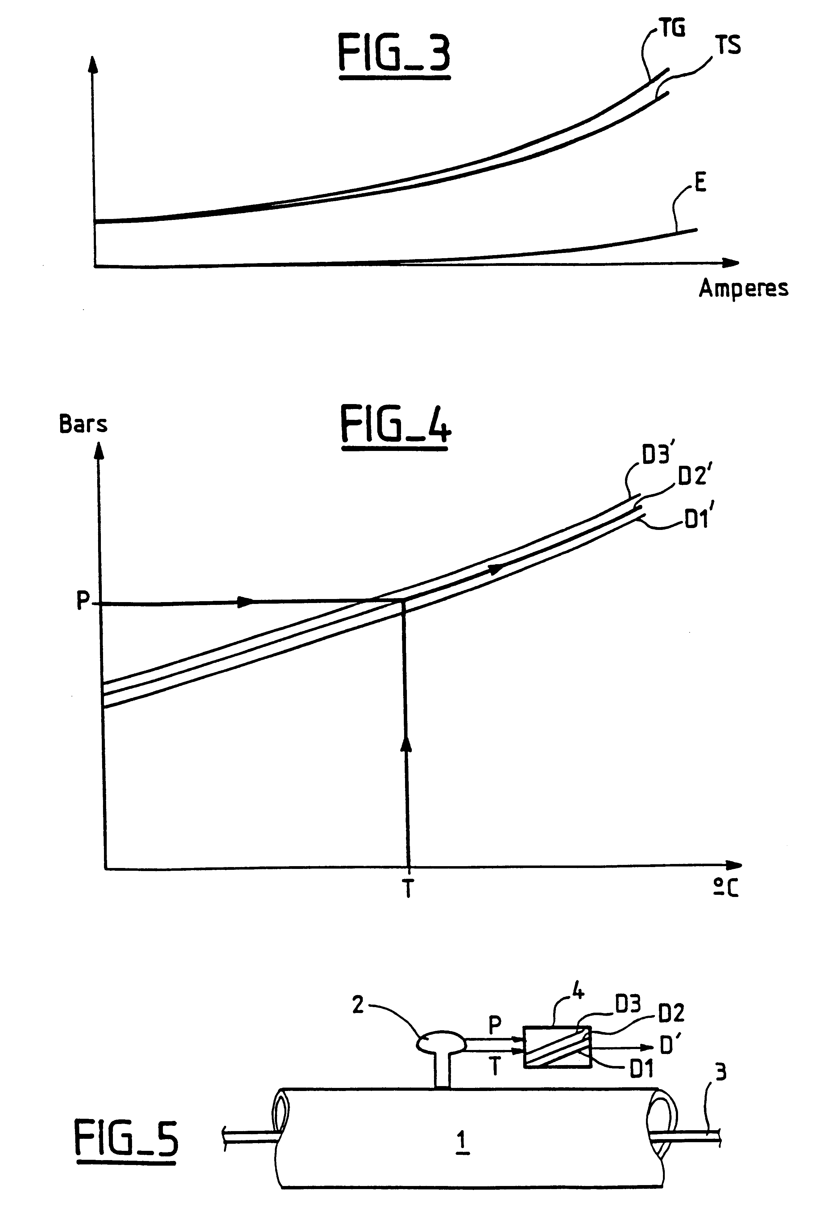
FIG. 3 shows the difference that exists between the temperature at the surface of the case of the buried metal-clad line and the mean temperature of the gas inside the case for increasing amounts of current being conveyed by the line conductor.
FIG. 4 is a graph analogous to that of FIG. 1 showing the method of the invention for measuring the dens...

Problems solved by technology

A large error in determining the density of the gas is due to the fact that the temperature sensor, regardless of whether or not it is integrated in the pressure sensor, is mounted on the outside surface of the case of the line such that the sensor measures the temperature of the gas only in a zone close to the surface of the case.
Unfortunately, this temperature measurement is generally not equal to the mean temperature of the gas inside the case, so it follows that the density as measured suffers from an error of the order of several percent.
This error penalizes protection of the metal-clad line.
Nevertheless, that solution is expensive to implement since it requires an additional physical magnitude to be measured, namely the current.
Unfortunately, the current carried by the metal-clad line can be measured only at an inlet stage, so it is necessary to disseminate this measured information over all of the density sensors mounted along the metal-clad line, and in practice that is complex and expensive.

Method used


Image

  • Method of measuring the density of a dielectric gas in a buried metal-clad line
  • Method of measuring the density of a dielectric gas in a buried metal-clad line
  • Method of measuring the density of a dielectric gas in a buried metal-clad line

Examples


Embodiment Construction

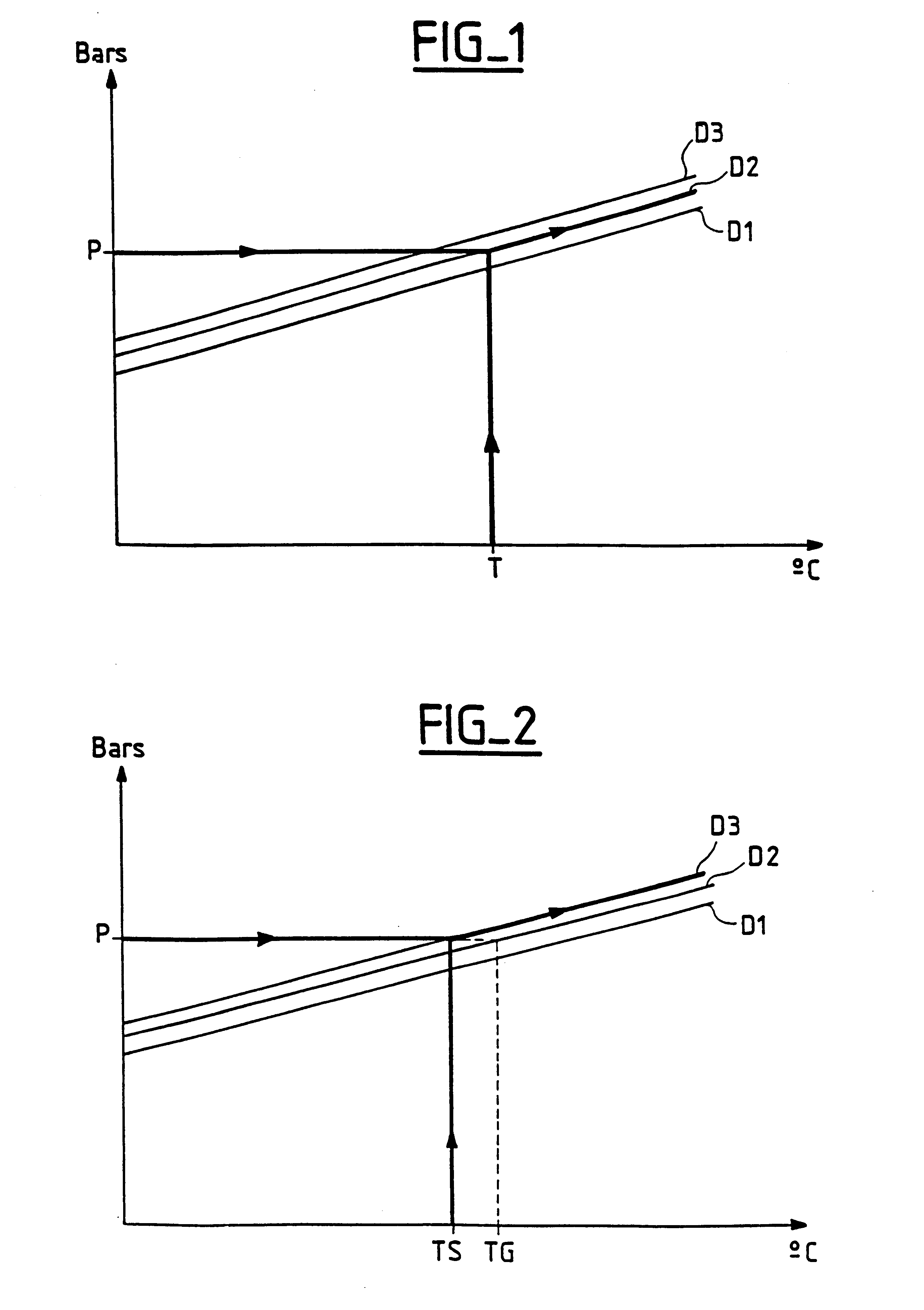
FIGS. 1 and 2 are described above.

In FIG. 3, the curve TG shows how the mean temperature of the gas inside the case of a buried metal-clad line varies as a function of increasing current carried by the conductor of the metal-clad line. The curve TS shows how the surface temperature of the case of the buried metal-clad line varies as a function of increasing current being carried by the conductor of the metal-clad line. The curves TS and TG are obtained by experimental measurements. The curve E represents the difference between the curves TG and TS. For each temperature value measured by a temperature sensor mounted on the outside surface of the case of the buried metal-clad line, there therefore corresponds a difference between the temperature as measured by the sensor and the mean temperature of the gas inside the case of the metal-clad line. And each difference between the temperature measured by the temperature sensor and the mean temperature of the gas inside the case of the met...


PUM


Abstract

A method of measuring the density of a dielectric gas under pressure in a buried metal-clad electricity line consists in measuring the pressure and the temperature of the dielectric gas by means of a sensor mounted on the case of the line, and in compensating the pressure measurement as a function of the temperature measurement using constant density curves that have been corrected on the basis of a curve representing the difference between the temperature at the surface of the case of the line and the mean temperature of the gas inside the line for increasing amounts of current carried by the line conductor.

Description

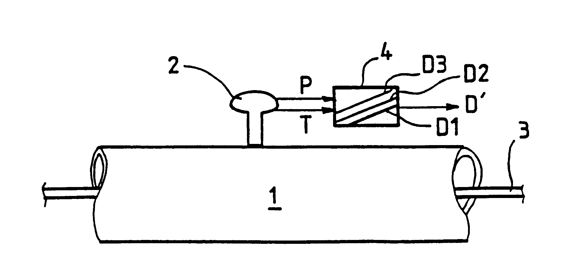
The invention relates to gas-insulated buried metal-clad electricity lines. Such a line comprises a cylindrical metal case filled with a dielectric gas under pressure, generally sulfur hexafluoride (SF.sub.6) or a mixture of sulfur hexafluoride and nitrogen, and an electrical conductor is disposed therein. In use, the case of the line is buried in the ground at a depth of two or more meters.The invention relates more particularly to a method of measuring the density of the dielectric gas under pressure inside the case of a buried metal-clad line.In general, measuring the density of the gas contained inside the case of a buried metal-clad line consists in measuring the pressure P and the temperature T of the gas and in compensating the pressure measurement as a function of the temperature measurement using constant density curves D1, D2, and D3 for the gas, as shown in FIG. 1. That compensation can be performed either in a data acquisition module receiving the pressure and temperatur...

Claims


Application Information

Patent Timeline
IPC IPC(8): H02B13/055H02B13/035H01H33/56H01H33/02G01N9/26G01N9/00H01B9/06
CPCH02B13/055H01H33/56H01H33/563H02B13/0655G01N9/00
Inventor MARMONIER, JEAN
Owner ALSTOM SA
Learn More