
Arrangement in terminating a cable

Inactive Publication Date: 2002-04-02
VETCO GRAY SCANDINAVIA
View PDF13 Cites 53 Cited by
  • Summary
  • Abstract
  • Description
  • Claims
  • Application Information

AI Technical Summary

Benefits of technology

A further object of the present invention is to indicate a device for terminating cables, which by underwater use provides sufficient sealing against penetration of sea water, and sufficient sealing against penetration of interior liquids and fluids.

Problems solved by technology

However, SE 504 919 does not suggest a joint withstanding water pressures at large depths.

Method used


Image

  • Arrangement in terminating a cable
  • Arrangement in terminating a cable
  • Arrangement in terminating a cable

Examples


Embodiment Construction

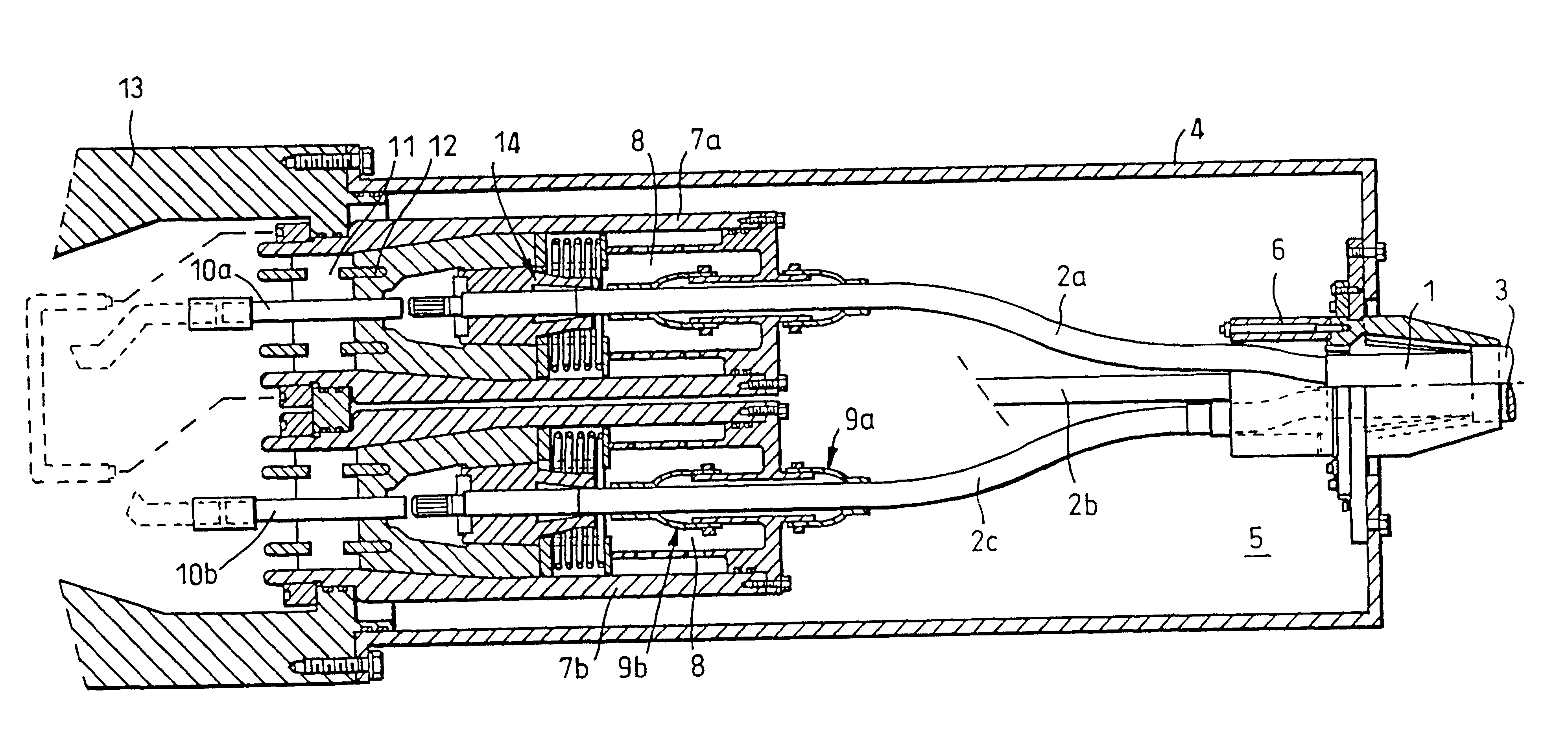
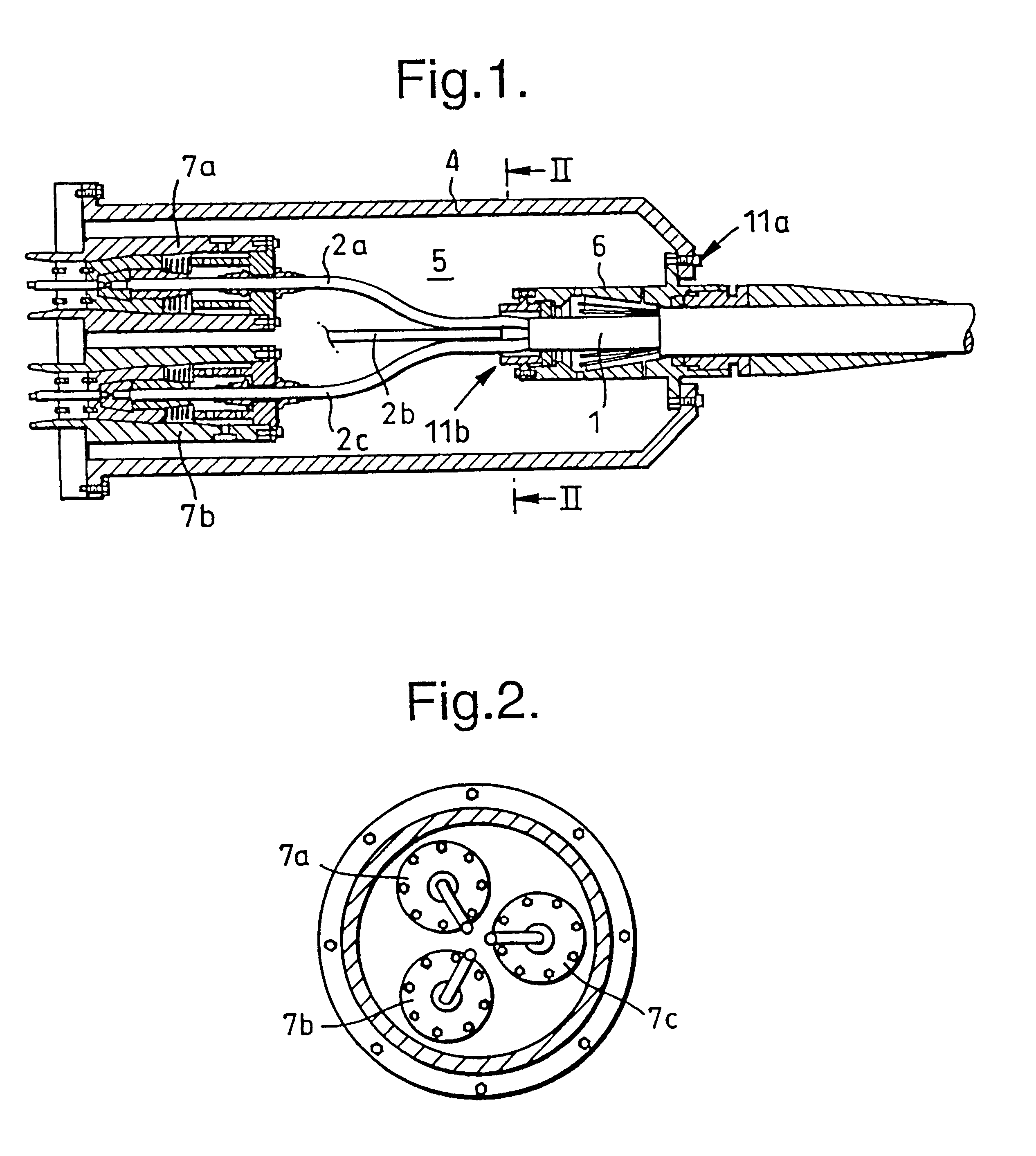
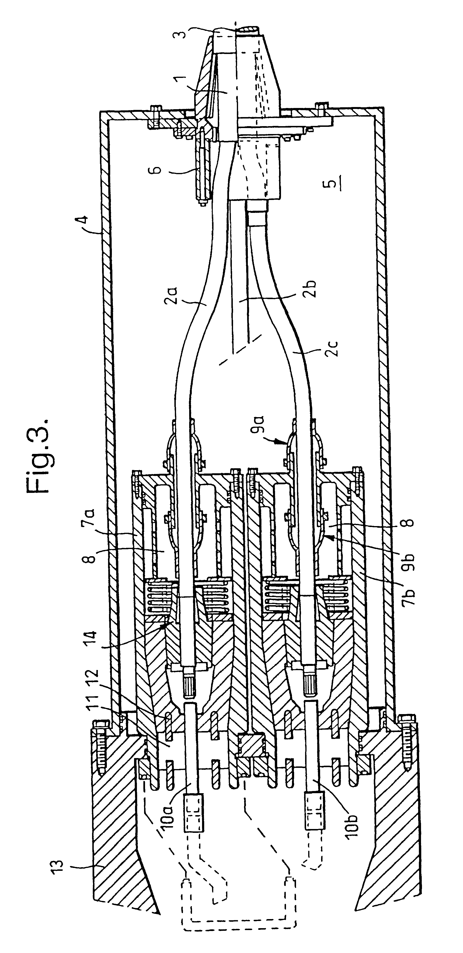
FIGS. 1 and 2 shows sectional side view and a sectional view, respectively, through an example of an embodiment for a device according to the invention, and in addition FIG. 3 shows a cable 1 comprising a number of insulated conductors, in this case the three conductors 2a, 2b and 2c, that are suitably insulated for high voltages, at the same time as the exterior of the cable 1 is provided with a common sheath 3, possibly also a reinforcement.

The embodiment of the cable 1, with the cable reinforcement and the exterior sheath 3, is according to FIGS. 1 and 2 terminated and fixed to a common outer metal terminating housing 4. The housing 4 is filled with a dielectric liquid 5, e.g. oil, and the single conductors 2a, 2b and 2c are sealed against the outer sheath 3 by means of a sealing device 6, in order to prevent the oil from leaking out into the surrounding water, or in order to prevent seawater from penetrating into the outer terminating housing 4. It can here be said that the meta...


PUM


Abstract

The present invention relates to a device for terminating cables (1), particularly for underwater termination of high voltage power cable and for conducting high voltage conductors in an electrical underwater apparatus, with the purpose of providing a liquid and water tight termination, at the same time as it provides pressure relief for vital components. According to this it is suggested that: each high voltage conductor (phase) (2a, 2b, 2c) is terminated in a separate, liquid filled and pressure compensated interior chamber (7a, 7b, 7c); conduction of the high voltage conductor from each interior chamber into attached electrical apparatus is carried out by means of a solid electrical conductor (10a, 10b, 10c), said conductor being fixed in an insulation material (11) which is liquid and gas tight, the solid electrical conductor and insulation material forming a gas and liquid tight barrier between the cable conductor and attached apparatus, and all interior chambers (7a, 7b, 7c) are adapted to a common, liquid filled and pressure compensated outer chamber (4).

Description

The present invention relates to a device for terminating cables, particularly underwater termination of high voltage power cables, more particularly a device for conducting high voltage conductors to an electric underwater apparatus.PRIOR ARTIn relation to the conduction of high voltage conductors for electric underwater equipment, e.g. underwater engines and underwater transformers, it is for several reasons very important that the conduction is as leak tight as possible. Further, it is important that the liquid containing housing, where the terminating operation is carried out, is pressure compensated as compared to the ambient sea pressure and further has a controlled dielectric environment.SE 504 919 (Johansson / Asea Brown Boweri AB) shows a cable termination for the connection of a high voltage cable with a solid insulation material, to an insulated conductor. In order to provide a suitable distribution of the electric field, a surrounding field directing means, a so called str...

Claims


Application Information

Patent Timeline
IPC IPC(8): H02G15/00H02G15/10H02G15/22H02G15/14H02G15/06H02G15/02
CPCH02G15/22H02G15/14H02G15/06
Inventor NYSVEEN, ARNEROCHE, SVENDGREUTER, FELIXJULKE, ELIASRHYNER, JAKOB
Owner VETCO GRAY SCANDINAVIA
Learn More