
Relative location detection sensor

a technology of relative location and detection sensor, which is applied in the direction of liquid/fluent solid measurement, instruments, machines/engines, etc., can solve the problems of actuating toroidal magnets, requiring operators, and exceedingly expensive preexisting configuration of tanks

Inactive Publication Date: 2002-04-02
SENGHAAS KARL A +4
View PDF9 Cites 26 Cited by
  • Summary
  • Abstract
  • Description
  • Claims
  • Application Information

AI Technical Summary

Problems solved by technology

One drawback of such a system is that an operator is required to observe the image, make an evaluation, and then report that information for further processing if so required.
To alter this preexisting configuration of the tanks would be exceedingly expensive and prohibitive to the employment of measuring devices that deviate from these constraints.
Specifically, the actuating toroidal magnets heretofore available had a limited strength and therefore required a more substantial lead area, sometimes achieved through elongation of the reed switch leads, in order for the switch to be influenceable to a closed configuration by the magnet.
This orientation, however, compromises not only the manufacture of the apparatus, but also its utility by restricting conditions for transport, as well as affecting the switch's sensitivity to the magnetic field produced from within the magnet-carrying float.
This necessitates personnel being employed for a highly intricate and repetitive task.
As a result, these assemblers are at risk of developing such conditions as carpal tunnel syndrome caused by the repetitive and tedious manual manipulation.
Because of the switch's elevated configuration, damage is likely if the switch is pressed against in the direction of the board.
This potential damage stems from the construction of the switch which includes a glass housing or sheath in which the reeds of the switch are intended to be protected for more reliable operation.
This can result in a distortion of the intended orientation of the interiorly located reed portions.
One of the drawbacks, however, of these softer metals is that they are more susceptible to plastic deformation, as opposed to elastic deformation, and will not regain their original positions once deformed, such as when being depressed toward the back board.
These changes in orientations are likely to adversely affect operation of the deformed switch.
If the back board is flexed as shown in FIG. 6, there is a likelihood that the reed switches mounted thereon will become misaligned to an extent that they fail to operate as designed.
The back board may be sufficiently flexed during transport to distort the position of the reeds inside the glass body of the switch so that it never regains its original and operatable configuration and therefore fails to operate upon installation.
As a result of this detrimental effect, systems manufactured according to these previous designs had to be transported under strict conditions to prevent the above described damage to the individual reed switches.
This is a significant disadvantage in that it requires the measuring apparatuses to either be assembled on site or to be transported in a rigidified and elongate state.
Each of these two options have proved burdensome.
If required to assemble the measuring apparatus on site, it is possible that the operation of the unit will be compromised because of inhospitable conditions experienced at many tank locations.
Among others, there will likely be dirt and dust that can affect the system's operation, as well as environmental conditions such as extreme heat that affects those personnel required for assembly.
Similarly disadvantageous is assembling these systems in a factory setting and transporting them to a remote site in an elongate rigid state using trucks with long beds.
Because most trucks are designed to carry articles of substantial weight when such a length is required, the employment of such trucks is exceedingly expensive in view of the apparatus' relative light weight, but long length.
This imposes not only manufacturing and assembly constraints on the previous designs, but it also necessitates the employment of experienced and trained personnel for installation.

Method used


Image

  • Relative location detection sensor
  • Relative location detection sensor
  • Relative location detection sensor

Examples


Embodiment Construction

As required, detailed embodiments of the present invention are disclosed herein; however, it is to be understood that the disclosed embodiments are merely exemplary of the invention that may be embodied in various and alternative forms. The figures are not necessarily to scale, some features may be exaggerated or minimized to show details of particular components. Therefore, specific structural and functional details disclosed herein are not to be interpreted as limiting, but merely as a basis for the claims and as a representative basis for teaching one skilled in the art to variously employ the present invention.

Furthermore, elements may be recited as being "coupled"; this terminology's use contemplates elements being connected together in such a way that there may be other components interstitially located between the specified elements, and that the elements so specified may be connected in fixed or movable relation one to the other. Certain components may be described as being ...


PUM


Abstract

In one embodiment, a relative location detection apparatus including a detection unit having a support board having a plurality of spaced reed switches mounted along a lengthwise axis of the support board. Each of the reed switches has a longitudinal axis oriented substantially perpendicular to the lengthwise axis of the support board. A high intensity magnet is coupled to the support board for movement relative to the support board and in a direction substantially parallel to the support board's lengthwise axis. The magnet has north and south poles that are oppositely positioned to one another and directed toward one another across a width of the support board and into periodic alignment with the longitudinal axes of the reed switches. The magnet has a magnetic force sufficiently focused so that the magnet actuates the reed switches individually thereby indicating the magnet's location.

Description

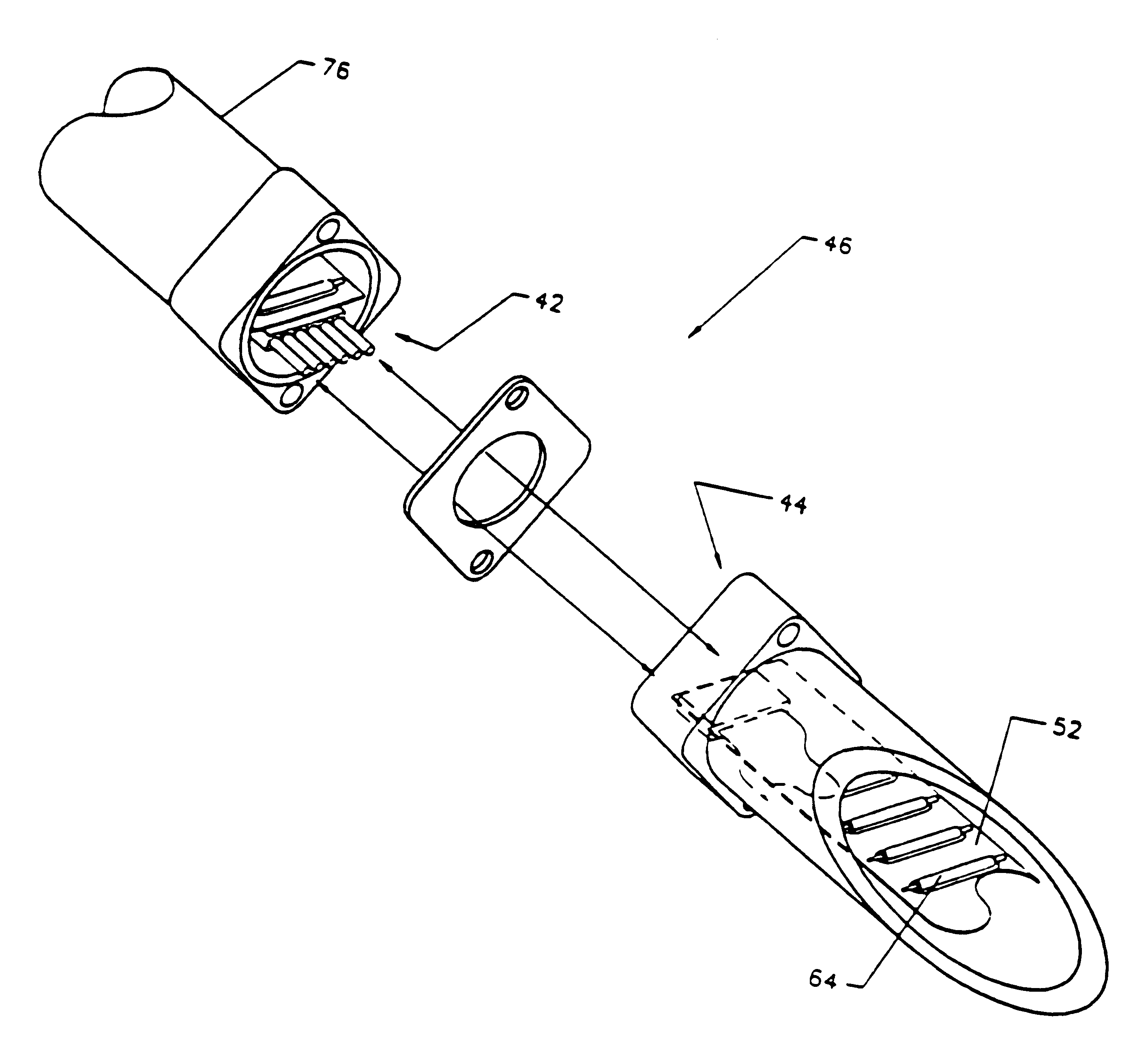
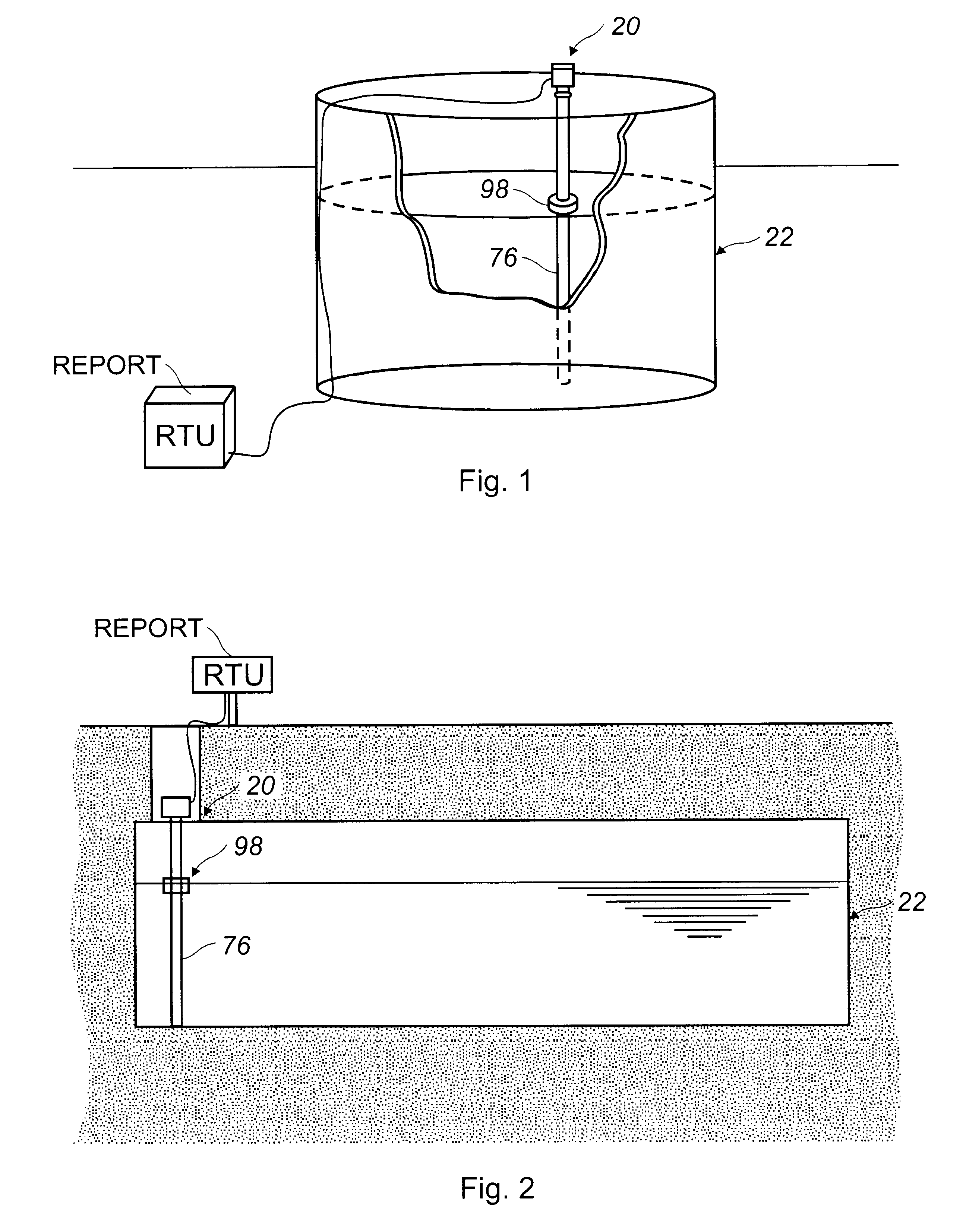
DESCRIPTION1. Technical FieldThis invention relates to systems and methods for determining the relative location of items with respect to one another. More particularly, it relates to methods and apparatus for detecting and reporting the relative location of an indicating unit traveling along the length of an elongate detector. In a preferred embodiment, this invention senses the position of a magnetic indicating unit relative to an elongate detector thereby determining and reporting the location of one or more fluid interfaces within a multi-phase fluid reservoir.2. Background ArtMany instances arise in both industrial and residential settings wherein the location of a reference point is desired to be detected and reported for evaluation. Many alternative methods may be employed for such purposes; an example is a video camera that either transmits or records a visual image of items that an operator desires to monitor. One drawback of such a system is that an operator is required to...

Claims


Application Information

Patent Timeline
Patent Type & Authority Patents(United States)
IPC IPC(8): G01F23/30G01F23/74G01F23/72H01H36/00
CPCG01F23/72G01F23/74H01H36/0006Y10S73/05Y02B90/224Y04S20/14H01H2300/03Y02B90/20
Inventor SENGHAAS, KARL A.SENGHAAS, PETERMICHALEC, JERZYKOLONKO, JR., PETER T.GOLD, JOHN H.
Owner SENGHAAS KARL A
Learn More