Eureka AIR delivers breakthrough ideas for toughest innovation challenges, trusted by R&D personnel around the world.

Apparatus and method for encoding and decoding digital video data

a digital video and video data technology, applied in the field of apparatus and methods for encoding and decoding digital video data, can solve the problems of difficult high-speed reproduction by reproducing only i-frames, inability to reproduce video data from a record medium in high-speed searching mode, etc., and achieve the effect of low and high search speed

Inactive Publication Date: 2002-03-26
SONY CORP
View PDF6 Cites 99 Cited by
  • Summary
  • Abstract
  • Description
  • Claims
  • Application Information

AI Technical Summary

Benefits of technology

A further object of the present invention is to provide a recording and reproducing technique which operate to achieve both high and low speed reproduction of variable rate compressed digital video data.
Still another object of the present invention is to provide a record medium having compressed digital video data stored thereon which is reproducible at low and high search speeds.

Problems solved by technology

However, when digital video data is MPEG compressed at a variable rate (e.g., the frame pattern of a GOP is variable) I-frames do not occur in the bit stream at known intervals thereof and, thus, high speed reproduction by reproducing only I-frames is difficult.
One problem with the above-discussed technique is its general inability to reproduce video data from a record medium in high-speed searching modes wherein it is desirable to successively reproduce I-frames occurring at relatively high intervals of time, for example, every 1, 2, 4, etc. seconds, in the bit stream.

Method used


Image

  • Apparatus and method for encoding and decoding digital video data
  • Apparatus and method for encoding and decoding digital video data
  • Apparatus and method for encoding and decoding digital video data

Examples


Embodiment Construction

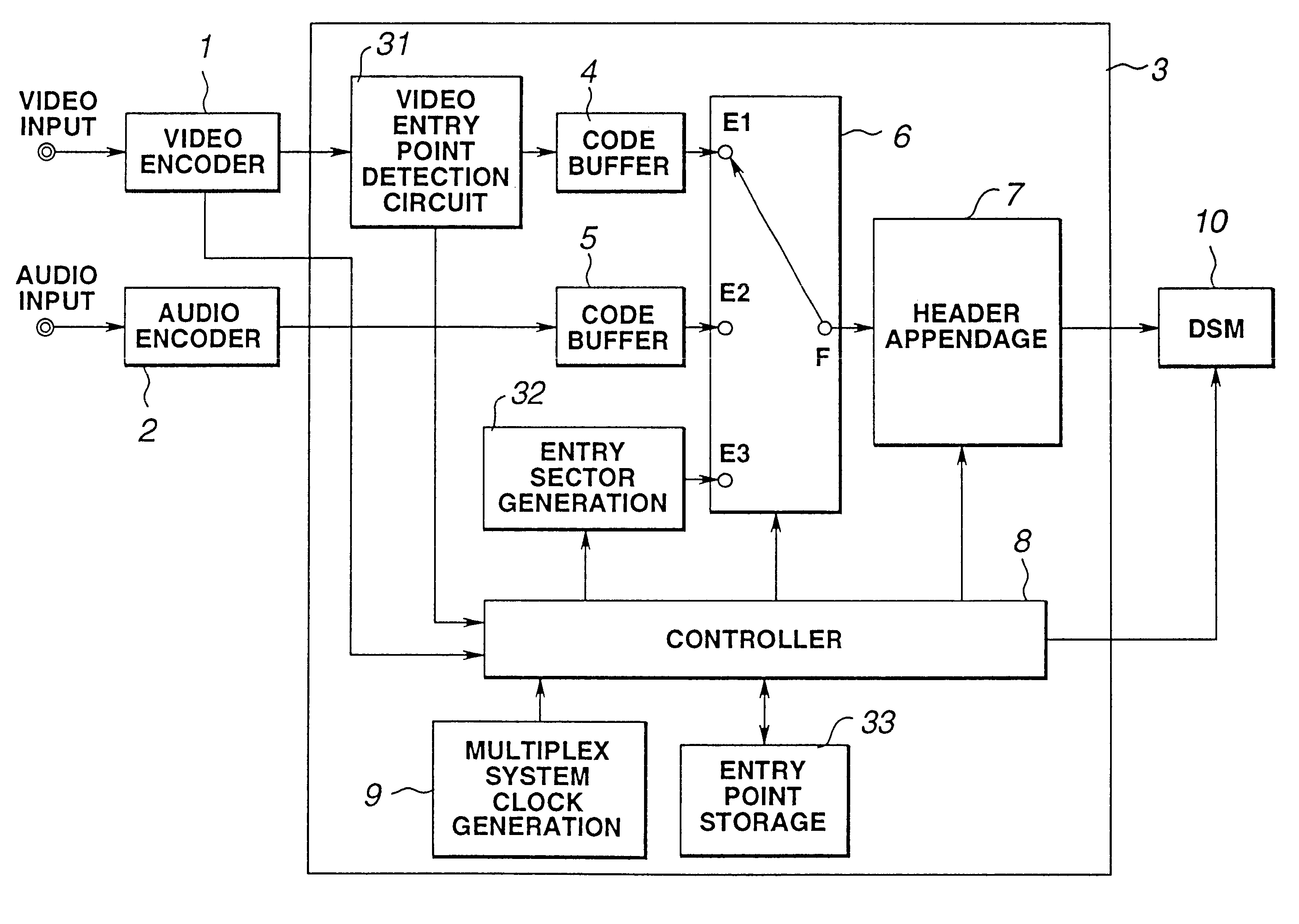
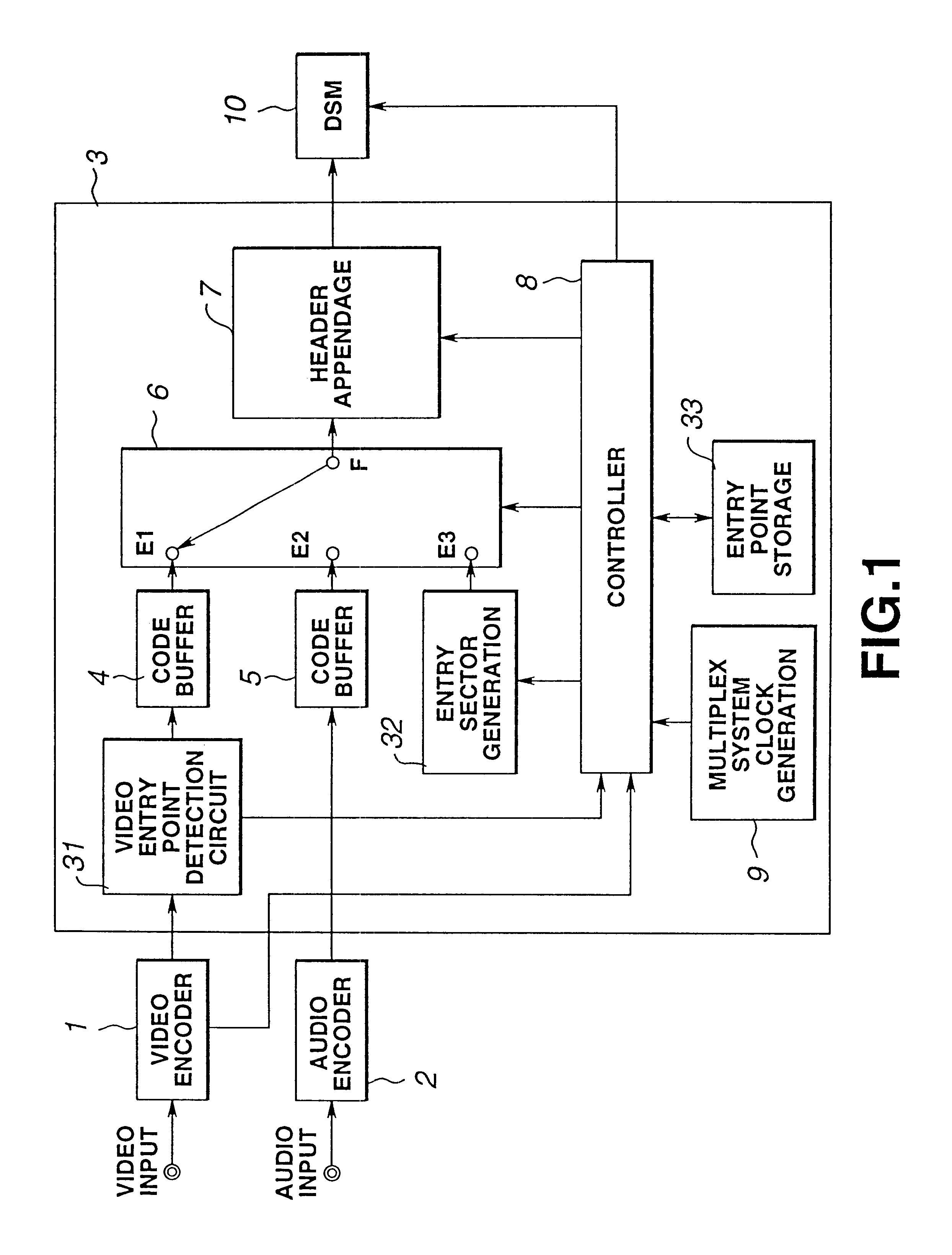
Referring to the drawings, and particularly to FIG. 1 thereof, a block diagram of apparatus for encoding digital video data (hereinafter encoding apparatus) in accordance with the present invention is shown. The encoding apparatus is shown as comprising a video encoder 1, an audio encoder 2, a multiplexing circuit 3 and a digital storage memory (DSM) 10. A digital video signal supplied to a video input terminal is supplied to video encoder 1 which compression encodes (i.e., intraframe and interframe encodes) the video signal in a manner well known in the art and which supplies the encoded video data to a video entry point detection circuit included in multiplexer 3. An digital audio signal supplied to an audio input terminal is supplied to audio encoder 2 which encodes the audio data therein in a manner well known in the art to produce packets of audio data and which supplies the packets of audio data to a code buffer 5 included in multiplexer 3.

In accordance with the present invent...


PUM

PropertyMeasurementUnit
timeaaaaaaaaaa
timeaaaaaaaaaa
timeaaaaaaaaaa

Abstract

Digital video data encoder and decoder operate to enable the low and high speed reproduction of variable rate encoded digital video data by reproducing and decoding intraframe encoded frames that are identified by previously reproduced intraframe encoded frames. In the encoder, digital video data is variable rate encoded, for example, intraframe and interframe encoded, entry points (i.e., beginning positions) of selected encoded video data are identified and which represent video frames that occur at predetermined intervals of time (e.g., 1, 2 and 4 seconds) in the video picture. Entry point data that identify these positions are generated and added to the encoded video data before the video data is recorded on a record medium. When the encoded data is reproduced from the record medium, the entry point data is extracted therefrom and stored, and a successive intraframe encoded frame identified by the extracted entry point data is reproduced and decoded. The invention further provides for a record medium having thereon the encoded digital video data, and also provides for an encoder and corresponding decoder which encode and decode, respectively, digital still image and audio data in which entry points refer to each of the still images and also to particular intervals of time of the audio data.

Description

The present invention relates to apparatus and method for encoding and decoding digital video data and, more particularly, to apparatus and method for encoding and decoding digital video data which enable low and high-speed reproduction of variable rate encoded digital video data, and also to a record medium having stored thereon variable rate encoded digital video data in a particular data structure which enables the low and high-speed reproduction thereof.As is known, MPEG compressed digital video data includes intraframe encoded digital video data ("I-frames") and interframe encoded digital video data including forward predictive encoded data ("P-frames") and bi-directionally predictive encoded data ("B-frames"). Generally, an I-frame is decoded without using data of other frames, but P and B-frames are decoded utilizing other frames.A bit stream of MPEG compressed digital video data generally is divided into groups of pictures (GOPs), and each GOP begins with an I-frame. When di...

Claims


Application Information

Patent Timeline
Patent Type & Authority Patents(United States)
IPC IPC(8): G06T9/00H04N7/52H04N7/64G11B20/10H04N5/78H04N5/92H04N7/24H04N19/102H04N19/134H04N19/162H04N19/423H04N19/46H04N19/50H04N19/503H04N19/577H04N19/65H04N19/70H04N19/89H04N21/2368H04N21/434H04N21/845
CPCG06T9/007H04N7/52H04N19/89H04N21/4341H04N21/8455H04N21/2368H04N21/4325H04N21/4334G11B27/005H04N5/92H04N21/235
Inventor FUJINAMI, YASUSHIYONEMITSU, JUNKAWAMURA, MAKOTOYAGASAKI, YOICHI
Owner SONY CORP
Why Eureka
Eureka Blog
Learn More