Antenna device and portable radio set
a portable radio and antenna device technology, applied in waveguide type devices, resonant antennas, non-interfering antenna combinations, etc., can solve the problems of deteriorating communication quality over telephones, increasing the specific absorption rate (sar) rate, and increasing the power per unit time and unit mass to be absorbed by a specific portion in the human body
- Summary
- Abstract
- Description
- Claims
- Application Information
AI Technical Summary
Problems solved by technology
Method used
Image

Examples
first practical embodiment
(2) First Practical Embodiment
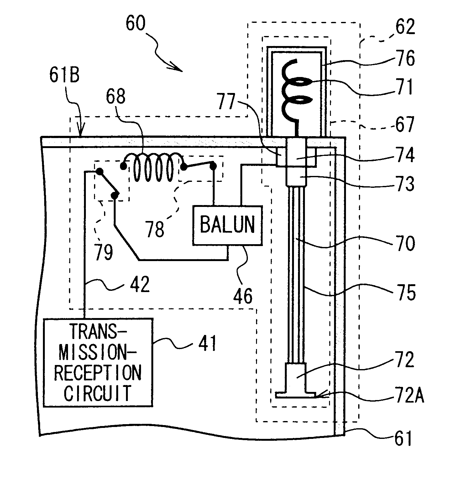
In FIG. 22, the numeral 60 denotes a cellular telephone in its entirety according to a first practical embodiment, being configured by comprising an antenna device 62 of a diversity reception system being provided in a housing 61 made of non-conductive member such as synthetic resin, etc.
This housing 61 is formed like a box where a speaker 63, a liquid crystal display section 64, various operation keys 65 and a microphone 66 are disposed in the front surface 61A.
In addition, in the antenna device 62, an antenna section 67 having a first antenna element is installed in the side of the back surface 61C of the upper surface 61B of the housing 61 which can be retracted and pulled out freely approximately in parallel in the elongated direction of this housing 61 (this hereinafter to be referred to as the box elongated direction) and as a second antenna element the first antenna element 68 of a fixed type formed by conductive line member being spirally rolled...
second practical embodiment
(3) Second Practical Embodiment
FIGS. 26A and 26B, in which the same numerals as in FIGS. 24A and 24B are given to show the corresponding portions, show a cellular telephone 80 according to the second practical embodiment, which is configured as in the cellular telephone 60 (FIGS. 24A and 24B) according to the above described first practical embodiment except the configuration of the antenna section 82 of the antenna device 81.
In FIGS. 27A and 27B in which the same numerals denotes the corresponding portions in FIGS. 24A and 24B, this antenna section 81 comprises a first antenna half part 83 and a second antenna half part 85, the first antenna half part 83 made of conductive cylindrical member with its lower end with which the power supplying member for the rod 72 is brought into electrical and mechanical connection and with its upper end where the stopper for pull-out 84 is provided, and the second antenna half part 85 made of conductive stick form member being inserted through the ...
third practical embodiment
(4) Third Practical Embodiment
FIGS. 28A and 28B, in which the same numerals as in FIGS. 24A and 24B are given to show the corresponding portions, show a cellular telephone 90 according to the third practical embodiment, which is configured as in the cellular telephone 60 (FIGS. 24A and 24B) according to the above described first practical embodiment except the disposing location as well as the posture of the first helical antenna 68 of the antenna device 91.
The first helical antenna 68 is disposed to have the first central axis being made approximately in parallel along the box elongated direction and approximately overlapping the extended line of the first central axis of the second helical antenna 71.
In addition, in the antenna device 91, when the antenna section 67 is thrust and pulled out, the rod antenna 70 is arranged so as to be able to be retracted and pulled out so that it is inserted through this first helical antenna 68 along the first central axis.
Thus, in the antenna de...
PUM
 Abstract
Description
Claims
Application Information
 - R&D
- Intellectual Property
- Life Sciences
- Materials
- Tech Scout
- Unparalleled Data Quality
- Higher Quality Content
- 60% Fewer Hallucinations
Browse by: Latest US Patents, China's latest patents, Technical Efficacy Thesaurus, Application Domain, Technology Topic, Popular Technical Reports.
© 2025 PatSnap. All rights reserved.Legal|Privacy policy|Modern Slavery Act Transparency Statement|Sitemap|About US| Contact US: help@patsnap.com