
Tooth type drill bit with secondary cutting elements and stress reducing tooth geometry

a drill bit and cutting element technology, applied in drill bits, earth drilling and mining, cutting machines, etc., can solve the problems of limited drilling applications of tooth type drill bits, limited drilling speed of bit bits, and rapid wear and/or breakage of teeth

Inactive Publication Date: 2002-02-19
REEDHYCALOG LP
View PDF21 Cites 14 Cited by
  • Summary
  • Abstract
  • Description
  • Claims
  • Application Information

AI Technical Summary

Problems solved by technology

The limited protrusion, blunt cutting edge, and narrow width of the cutting inserts, however, limit how fast the bit can drill.
Encounters with hard, tough formations often cause very rapid wear and / or breakage of the teeth.
The drilling applications for tooth type bits have been limited by the inability of these bits to drill hard rock.
Since it is time consuming (and therefore expensive) to change the rock bit each time a new layer of rock is encountered, a bit chosen to drill both types of formations is often running under less than optimum drilling conditions.
However, when the majority of the layers are soft rock, a tooth bit can be destroyed by a relatively thin layer of hard, tough rock.
If he uses an insert type bit he can easily drill through the hard formations, but he will sacrifice drilling speed and drive up the cost.
If the driller uses a tooth type bit, he will get economical, high drilling speeds but he risks destruction of the bit and the downtime required to replace it.
Although advances in hardfacing materials and methods, and the advent of RSSDPM processing have made tooth type bits more durable in recent years, the problem remains.

Method used


Image

  • Tooth type drill bit with secondary cutting elements and stress reducing tooth geometry
  • Tooth type drill bit with secondary cutting elements and stress reducing tooth geometry
  • Tooth type drill bit with secondary cutting elements and stress reducing tooth geometry

Examples


Embodiment Construction

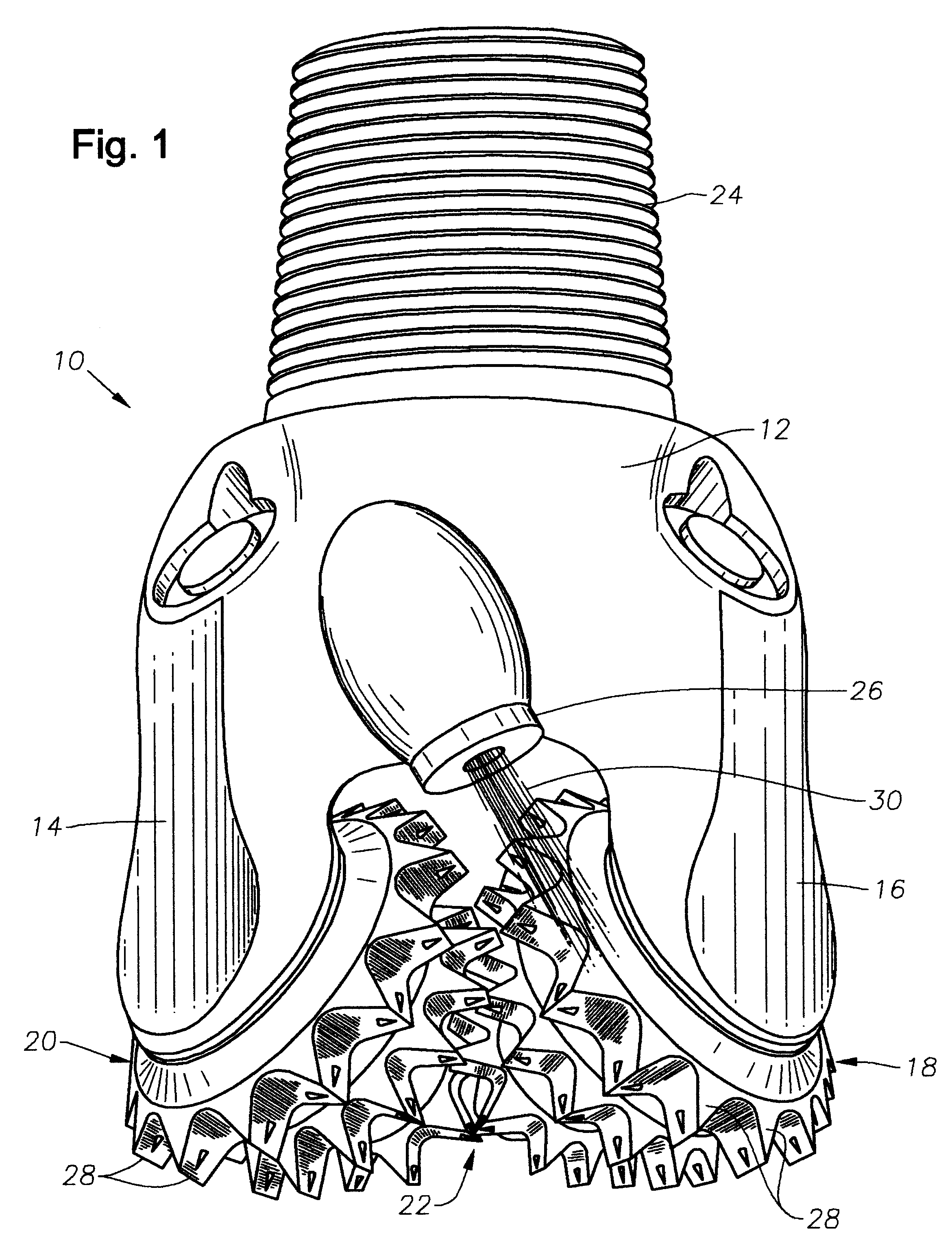
A typical tooth type bit is shown as numeral 10 of FIG. 1. Typically, tooth bits have a body 12 with three legs 14, 16 (only two are shown). Upon each leg is mounted a rolling cutter 18, 20, 22. During operation, the bit 10 is secured to drill pipe (not shown) by threads 24. The drill pipe is rotated at the surface and drilling fluid is pumped to the bit 10 and exits through one or more nozzles 26. The weight of the drilling string forces the cutting teeth 28 of the cutters 18, 20, 22 into the earth, and, as the bit 10 is rotated, the earth causes the cutters 18, 20, 22 to rotate upon the legs 14, 16 effecting a drilling action. The drilling fluid 30 exiting the nozzles 26 flush away the earth removed by the cutters 18, 20, 22 and can remove cuttings which often adhere to the cutters 18, 20, 22.

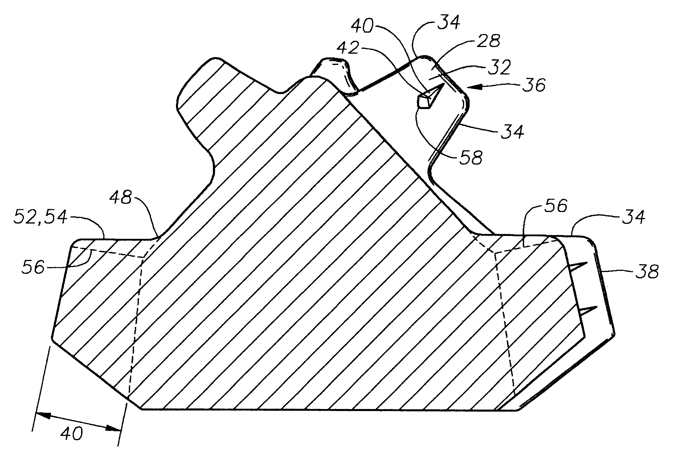
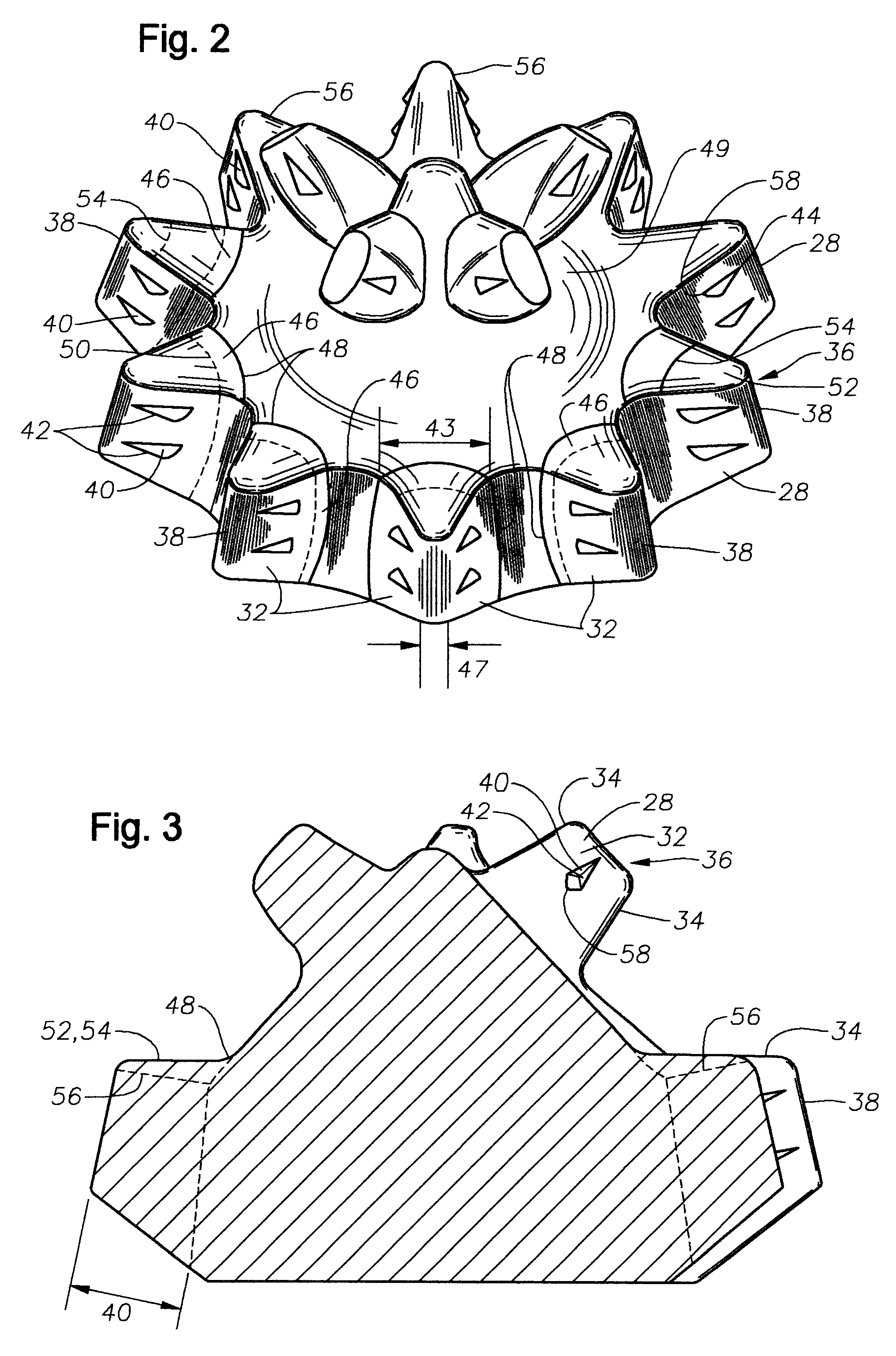
As shown in FIGS. 1-3 the teeth 28 are generally wedge shaped with a pair of relatively flat flanks 32 and a pair of curved end surfaces 34. The two flanks 32 are joined at the top 36 of the ...


PUM


Abstract

Disclosed is a tooth type rolling cutter earth boring drill bit with secondary cutting elements on the tooth surfaces. The secondary cutting elements provide additional, relatively sharp edges that help cut hard rock. The teeth also have convex radiused buttresses at their bases to reduce the stresses the teeth experience when drilling through extremely hard rock. This allows the tooth bit to survive the high loads encountered when drilling hard, tough rock formations, without breaking the teeth. The combination of teeth with secondary cutting elements and convex radiused buttresses at their base provide a tooth type rotary drill bit that has superior resistance to wear and breakage when drilling through hard, tough rock without significantly reducing the drilling rate of penetration when drilling through soft rock.

Description

1. Field of the InventionThe present invention relates to earth boring bits used in the retrieval of oil, natural gas, and other earth minerals. In particular, the invention is a new rolling cutter drill bit with a tooth structure having integral secondary cutting elements and a reduced stress tooth geometry.2. Description of the Related ArtEarth boring bits used for the recovery of petroleum and other minerals from the earth are generally of either the fixed cutter type or rolling cutter type. A fixed cutter drill bit has a plurality of cutting edges that are pushed into and dragged through the earth. This type of bit removes the earth primarily by shearing and scraping.Rolling cutter drill bits (also known as rock bits) have cutting teeth or cutting inserts arranged upon one or more rotating cutters. Typically, the bit body has three cantilevered bearing spindles with frusto-conically shaped rolling cutters arranged on them. When the bit body is rotated and weight is applied, the ...

Claims


Application Information

Patent Timeline
IPC IPC(8): E21B10/16E21B10/08
CPCE21B10/16
Inventor VUYK, JR., ADRIAN
Owner REEDHYCALOG LP
Learn More