
Enhancement of storm location from a single moving platform

a moving platform and location technology, applied in meteorology, instruments, measurement devices, etc., can solve problems such as lightning discharg

Inactive Publication Date: 2002-02-19
RYAN INT OHIO
View PDF16 Cites 74 Cited by
  • Summary
  • Abstract
  • Description
  • Claims
  • Application Information

AI Technical Summary

Benefits of technology

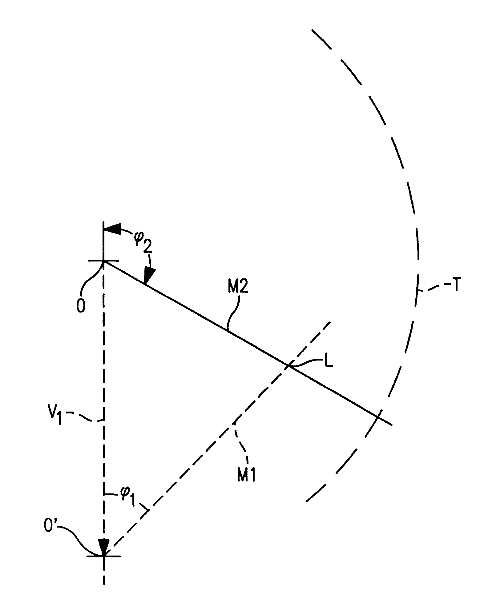
Accordingly, the invention provides an enhanced weather mapping system for determining location of lightning related weather activity relative to a moving platform, such as an aircraft. The invention employs a receiver on board the platform which is responsive to electrical signals generated by the lightning in a predetermined frequency band. Associated with the receiver are means for determining the azimuth of a source of the electrical signals relative to the receiver. The data, indicating the azimuth from the receiver to the signal source is stored. After the platform has moved, the stored azimuth information is updated so as to correct for the motion of the receiver. Finally, a determination of weather pattern location is obtained by combining updated azimuth indications with more current azimuth information for estimating the location of a weather pattern at the intersection of a more current azimuth indication and an updated azimuth indication. Because the motion of the platform (i.e. the aircraft) is typically at a much higher rate than the motion of the weather activity, there is minimal error introduced by ignoring any weather motion.

Problems solved by technology

The violent air currents that are hazardous to aircraft flight produce the lightning discharge.

Method used


Image

  • Enhancement of storm location from a single moving platform
  • Enhancement of storm location from a single moving platform
  • Enhancement of storm location from a single moving platform

Examples


Embodiment Construction

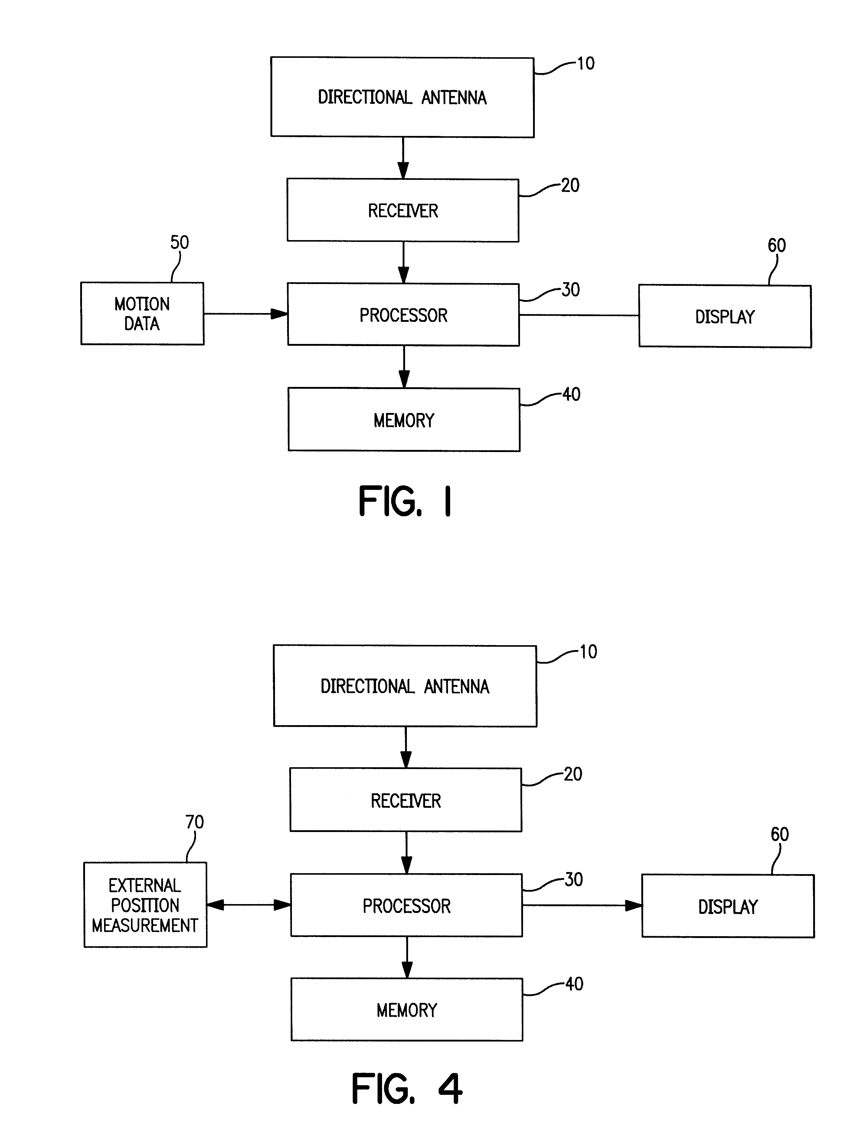
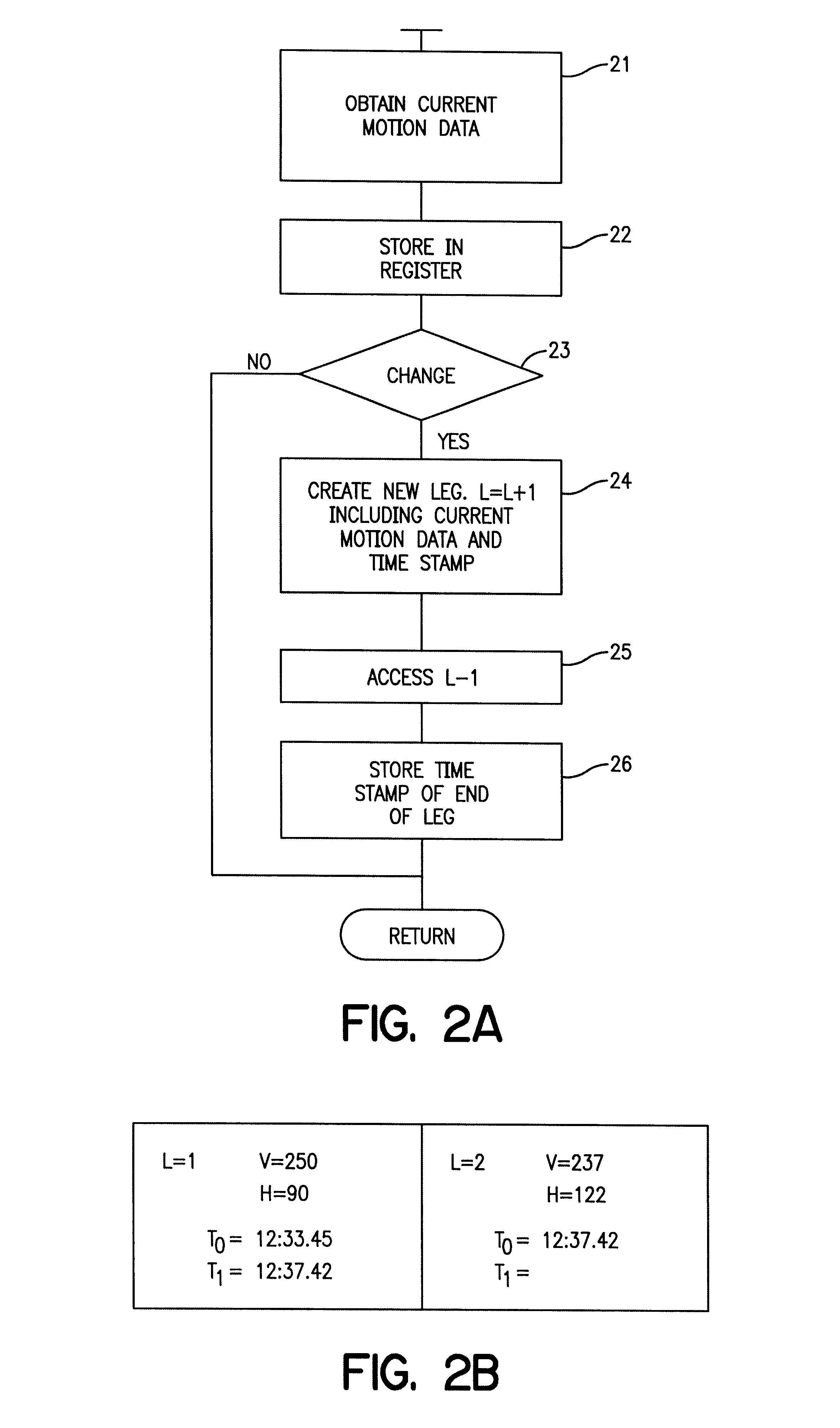
FIG. 1 is a block diagram illustrating several components of an embodiment of the invention. In particular, a directional antenna 10 provides signals to a receiver 20. The directional antenna 10 and receiver 20 may be tuned to an appropriate frequency band as is described for example in Ryan U.S. Pat. No. 4,023,408 (the disclosure of which is incorporated herein by reference), so as to focus on signals generated by lightning. Those skilled in the art will understand that although the drawing shows only a single connection between the directional antenna 10 and the receiver 20, in practice, there are several signals provided by the antenna to the receiver so that the receiver can perform its function. In any event, the receiver is tuned and provides a plurality of signals to the processor 30. The processor 30 is capable of generating an azimuth indication from the signals provided by the receiver 20, all as described in U.S. Pat. No. 4,023,408. The memory 40 is coupled to the process...


PUM


Abstract

The location of weather activity from a moving platform such as an aircraft is enhanced using triangulation in time. More particularly, a first measurement of the weather activity is made relative to the aircraft at a first time. A second measurement of the location of the weather activity is made from the aircraft at a second period in time. The first measurement is modified or updated to correct for the change in position of the aircraft between the first and second measurements and then the modified data is compared with the data of the second measurement to enhance the location of the weather activity.

Description

The invention relates to storm mapping systems.BACKGROUND OF INVENTIONOver the past 25 years, the aviation industry has been the beneficiary of improved storm mapping systems. See U.S. Pat. Nos. 4,023,408 and 4,395,906. Those storm mapping systems took advantage of the correlation between thunderstorms and lightning discharges. The violent air currents that are hazardous to aircraft flight produce the lightning discharge. The lightning discharge also generates electromagnetic radio waves. Directional receiving apparatus, located on board an aircraft, can determine the direction of the lightning discharge. Some information is available about the distance of the discharge as well. By receiving and storing this direction and distance information, a map is formed from the stored data, to give the pilot a plan view image of the storm activity relative to the aircraft.From the inception of the popularity of these devices, it was known that there was a significant difference in the precisi...

Claims


Application Information

Patent Timeline
IPC IPC(8): G01W1/10
CPCG01W1/10
Inventor RYAN, PAUL A.RYAN, DEAN E.
Owner RYAN INT OHIO
Learn More