Eliminating the Raman effect by modulating polarization

a technology of modulating polarization and raman, which is applied in the direction of optics, instruments, optical elements, etc., can solve the problems of limited pump power and signal power, and achieve the effect of increasing power in a repeaterless link

Inactive Publication Date: 2002-02-05
RPX CORP
View PDF8 Cites 20 Cited by
  • Summary
  • Abstract
  • Description
  • Claims
  • Application Information

AI Technical Summary

Benefits of technology

The invention proposes a solution that makes it possible to increase power in a repeaterless link. It goes against the general prejudice in the state of the art by p

Problems solved by technology

However, the signal power and the pump power that can be injected are limited by various non-linear effects, and in particular the Brillouin effect, the Kerr effect, and the Raman effect.

Method used


Image

  • Eliminating the Raman effect by modulating polarization
  • Eliminating the Raman effect by modulating polarization

Examples


Embodiment Construction

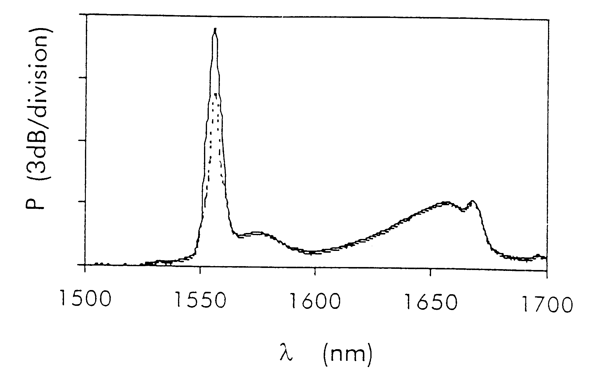
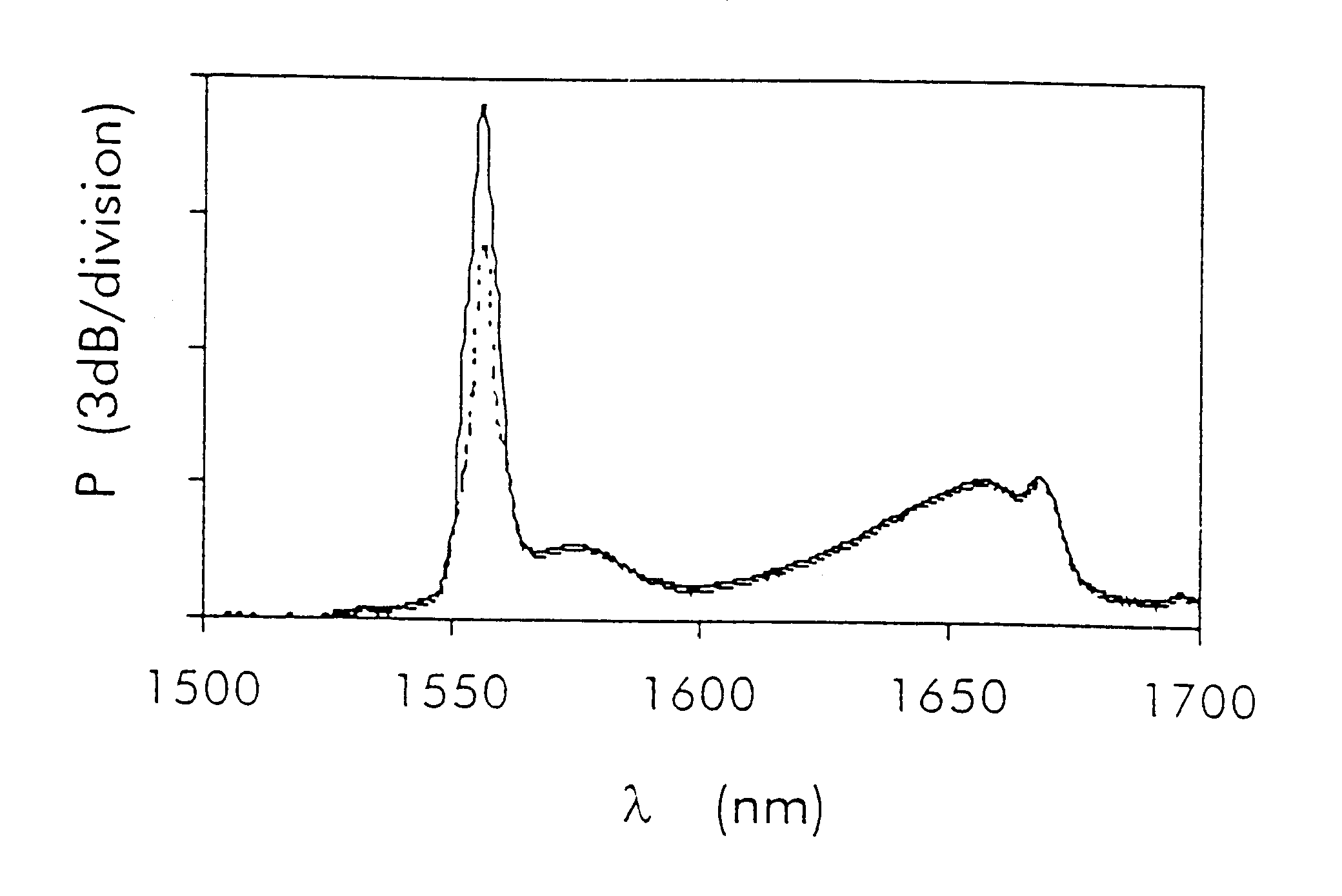
In a repeaterless optical fiber transmission system, the invention proposes scrambling the polarization of the injected lightwaves so as to limit the amount of energy that is transferred by the Raman effect. This makes it possible to increase the amount of power that is injected into the link. The invention applies to all types of lightwaves: signal waves, signal waves when WDM is used, pump waves, or both signal and pump waves.

The Figure is a graph of power as a function of wavelength. The abscissa is graduated in nanometers and the ordinate is graduated at 3 dB per division. The Figure shows the power after propagating for 100 km in a pure silica core fiber (PSCF). The dashed line corresponds to a transmission system without polarization scrambling while the continuous line shows power in a transmission system of the invention having polarization scrambling means. In the example shown in the Figure, these means are constituted by a polarization scrambler which rotates the polariza...


PUM


Abstract

In a repeaterless optical fiber transmission system, the invention proposes providing polarization scrambling means. This makes it possible to limit the amount of energy that is transferred by the Raman effect, while increasing the amount of power that can be injected into the link. The invention is equally applicable to the lightwaves used for carrying information and to the lightwaves used for pumping.

Description

The present invention relates to the field of transmission by optical fiber. More particularly, the invention relates to "repeaterless" links. Such links are defined by the fact that they use electrically active elements only in the end equipments.Repeaterless optical fiber links have the particular feature of requiring very high optical power levels to be injected into the optical fiber in order to reach long distances. Two types of lightwave are injected into the fiber. The first type is the signal wave at about 1550 nm, which wave is modulated to carry the information that is to be transmitted. The second type of lightwave is a "pump" lightwave in the 1400 nm to 1500 nm wavelength range, and is constituted by continuous power injected into the optical fiber so as to amplify the signal.Numerous variants exist for using the pump wave. The pump wave can be emitted from the send terminal or from the receive terminal. The commonest scheme consists in placing a length of doped fiber in...

Claims


Application Information

Patent Timeline
IPC IPC(8): H04B10/18H04B10/135H04B10/2537G02B6/00H04B10/532
CPCH04B10/532H04B10/2537
Inventor BLONDEL, JEAN-PIERREBRANDON, ERIC
Owner RPX CORP
Why Eureka
Try Eureka