
Modular jumper cable

a jumper cable and module technology, applied in the direction of cell components, cell component details, coupling device connections, etc., can solve the problems of creating a hazardous condition, user exerting considerable effort, and existing commercially available jumper cables of the type described above have several undesirable characteristics

Inactive Publication Date: 2002-02-05
FLOYD MARVIN
View PDF11 Cites 20 Cited by
  • Summary
  • Abstract
  • Description
  • Claims
  • Application Information

AI Technical Summary

Benefits of technology

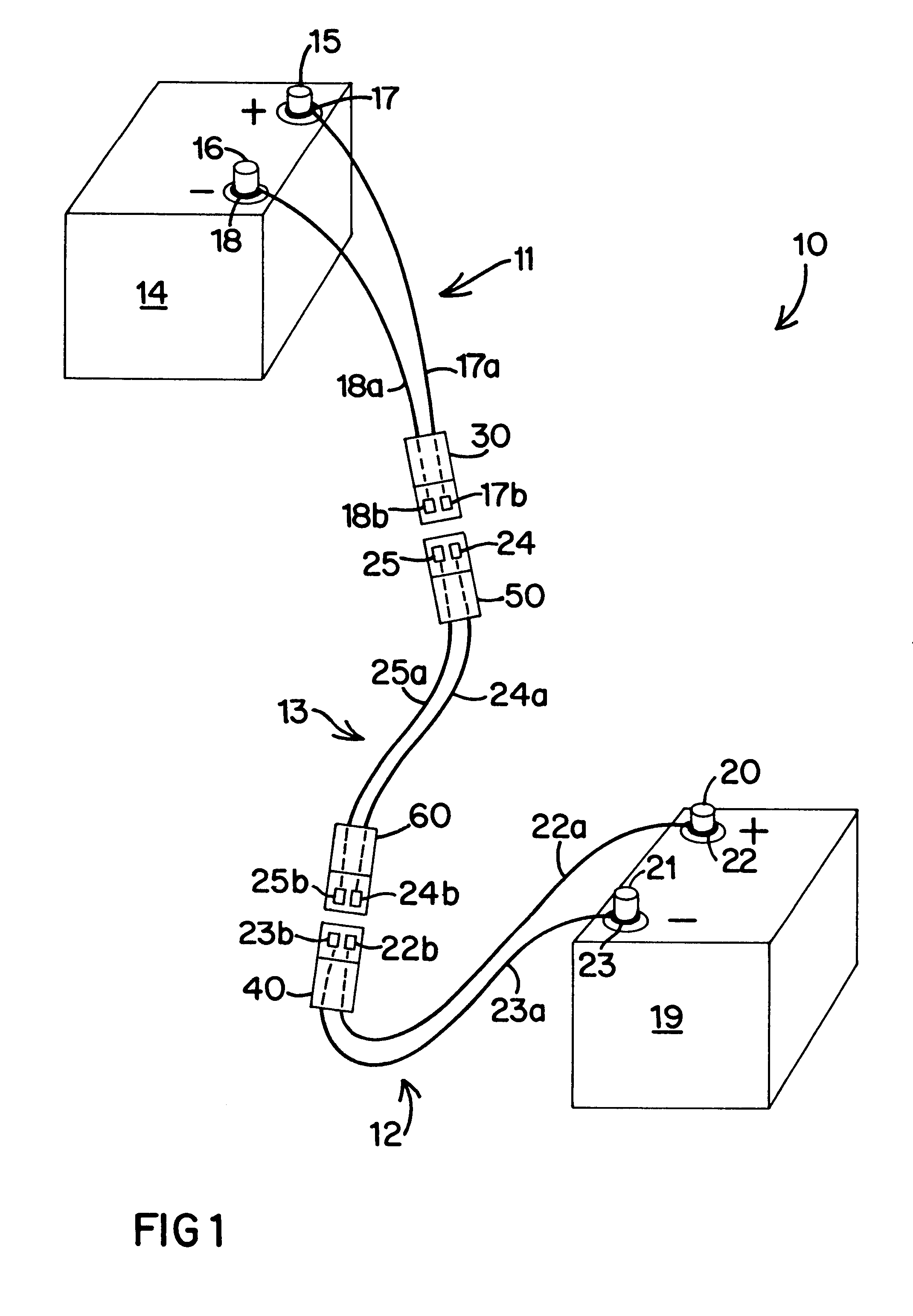
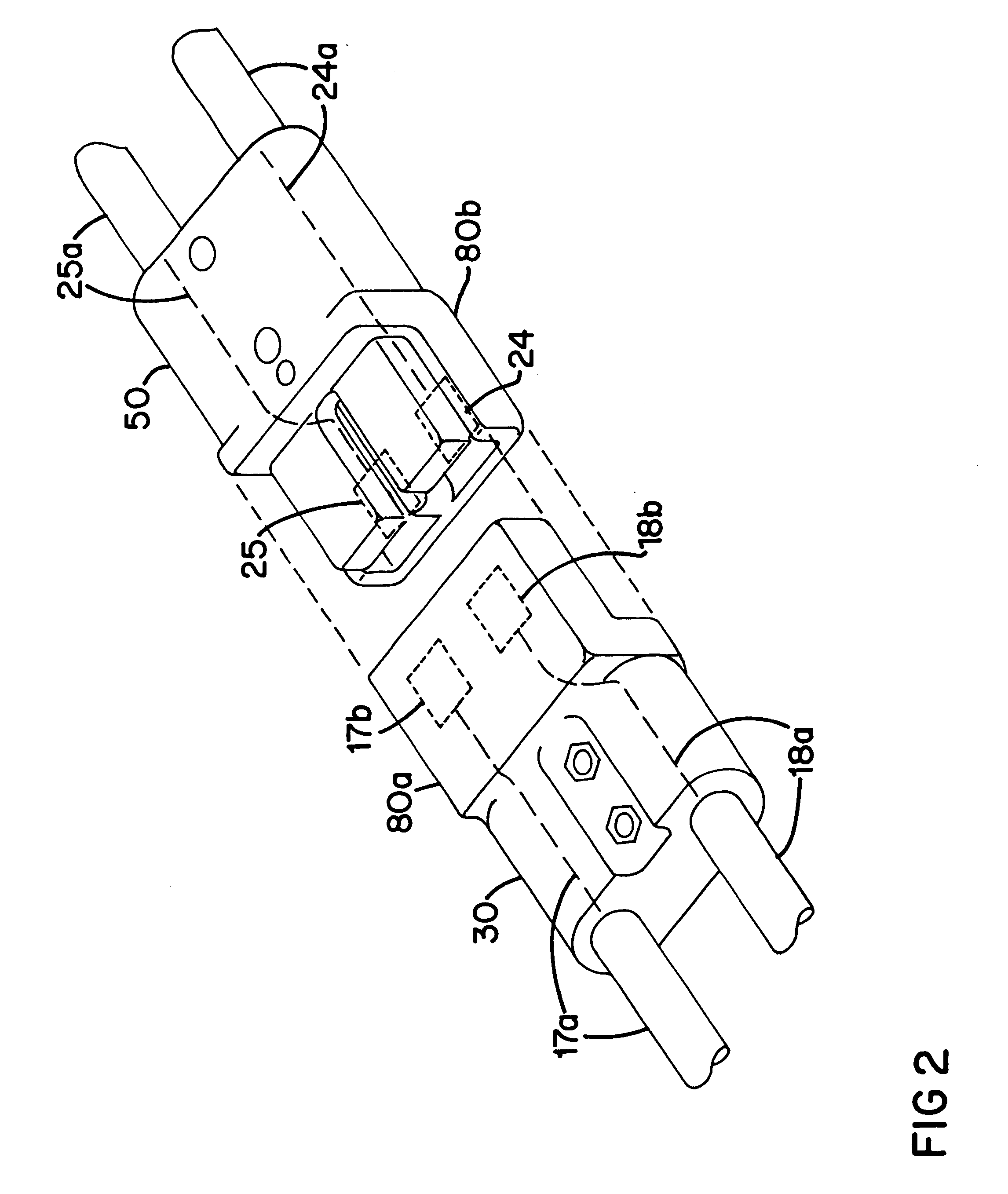
These and other objects are achieved in the present invention through the use of a modular jumper cable system that includes easy-to-use connectors. The system includes three components. The first is an intermediate cable having an isolated pair of conductive wires or cords. Each of the two ends of the intermediate cable terminates in connector block having two separated ports, corresponding to the conductive wires. The other two components of the system are battery cables. Each of the battery cables includes an isolated pair of conductive wires or cords. At one end of each battery cable is a pair of battery-post loops, one for each conductive wire, to be easily applied to the positive and negative posts of a battery. The opposing end of each battery cable includes an interface connector having two separated ports, corresponding to the respective conductive wires. The interface connector is designed to be releasably and easily connected to one of the connector blocks of the intermediate cable. Preferably, the respective connectors can only be connected together one way such that when the intermediate and battery cables are connected together, like battery terminals are connected together.

Problems solved by technology

Failure to connect positive to positive and negative to negative will prevent charging and could create a hazardous condition.
Unfortunately, existing commercially available jumper cables of the type described above have several undesirable characteristics.
First, the spring-loaded alligator clamps require the user to exert considerable effort to force open the jaws wide enough to accommodate the battery terminals.
For individuals having inadequate grip strength, the task may be impossible to complete.
In that situation, the goal of charging a dead battery may not be achieved.
Dependent upon the surrounding conditions, such as the time of day, the weather, and the proximity of the dead battery to well-lit and / or populated areas, the inability to charge a dead battery may be a frightening event.
Again, dependent upon surrounding conditions, it can be difficult to observe all of the connections and make sure that the positive terminals are connected together and the negative terminals are connected together.
Yet another concern associated with the existing unitary jumper cables is the limitation on the length of the cables used.
However, there are numerous situations where that may be difficult including, but not limited to, two vehicles that cannot be placed close to one another.
However, it continues to include the difficult-to-operate alligator clamps.
The prior systems fail to provide a safe and easy-to-use jumper system to ensure that battery charging can be effected.

Method used


Image

  • Modular jumper cable
  • Modular jumper cable
  • Modular jumper cable

Examples


Embodiment Construction

A modular jumper cable system 10 of the present invention is shown in FIG. 1. The system 10 includes a first battery-connecting cable unit 11, a second battery-connecting cable unit 12, and an intermediate cable connector 13. The first cable unit 11 is connectable to a first battery 14 having a positive battery terminal 15 and a negative battery terminal 16. The first cable unit 11 is detachably connectable to the first battery 14 by way of a first battery-coupling device 17 and a second battery-coupling device 18. The first and second battery coupling devices 17,18 may be any type of easy-to-attach termination of a conductive cable, but are preferably formed of conductive material, such as a metal, in a shape including, but not limited to, an eyelet (FIG. 4) or a horseshoe (FIG. 3). A terminal cap may be applied to the terminals 15,16, in order to retain the devices 17,18, thereon, if desired.

Coupling device 17 is preferably permanently joined to a first conductor cable 17a, such a...


PUM

PropertyMeasurementUnit
conductiveaaaaaaaaaa
forceaaaaaaaaaa
grip strengthaaaaaaaaaa

Abstract

A modular jumper cable system for connecting two batteries together. The cable system includes two cable units, one for detachable connection to one battery, the other for detachable connection to the other battery. The cable units may be connected to the batteries' terminals by easy-to-operate connectors, such as conductive eyelets. The system further includes an intermediate cable connector for joining the two cable units together. The linking connection ends of the cable units and the intermediate connector are formed of releasable connection devices that must be oriented in only one way to complete a connection. The connection devices ensure that like terminals of the batteries will be connected to one another. Difficult-to-manipulate alligator clamps are avoided in the modular jumper cable system.

Description

1. Field of the InventionThe present invention relates to battery-charging jumper cables. More particularly, the present invention relates to modular jumper cables. Still more particularly, the present invention relates to a jumper cable system including a first cable to connect to a first battery, a second cable to connect to a second battery, and an intermediate cable with quick disconnect for connecting the first and second cables together.2. Description of the Prior ArtBattery jumper cables are used to establish a circuit between a charged battery and a discharged battery such that the charged battery can be used to start the discharged battery. The jumper cables generally available commercially include two insulated conductive cables each terminating at opposing ends with connectors, all as a unitary device. The connectors most commonly forming part of these devices are spring-loaded sawtooth clamps are identified as alligator clamps.The jumper cables with alligator clamps prov...

Claims


Application Information

Patent Timeline
Patent Type & Authority Patents(United States)
IPC IPC(8): H01R11/28H01R11/11H01R13/642H01M2/30H01M50/55H01M50/553
CPCH01R13/642H01R11/288H01M2/30Y02E60/10H01M50/553H01M50/55
Inventor FLOYD, MARVIN
Owner FLOYD MARVIN
Learn More