Control apparatus for spark ignition type direct injection engine

Inactive Publication Date: 2001-12-04
MAZDA MOTOR CORP
View PDF4 Cites 26 Cited by
  • Summary
  • Abstract
  • Description
  • Claims
  • Application Information

AI Technical Summary

Problems solved by technology

On the other hand, since extra fuel is consumed to only refresh the catalyst, fuel economy suffers.
However, since the additional fuel has nearly no contribution to the engine output, fuel economy may deteriorate considerably.
On the other hand, the surrounding lean air-fuel mixture burns slowly, and since some mixture is exhausted before it completely burns, the CO concentration in this exhaust gas becomes very high.
That is, when the fuel injection quantity of trailing injection is less than 20% of the total injection quantity, it becomes difficult to form an over-enriched air-fuel mixture with high ignitability around the spark plug of the engine.
By contrast, when the fuel injection quantity of trailing injection exceeds 80% of the total injection quantity, the air-fuel mixture around the spark plug becomes too rich and the surrounding lean air-fuel mixture becomes too lean, thus disturbing smooth flame propagation.
As shown in, e.g., FIG. 9, if the trailing injection quantity qinjd is less than 20% of the total injection quantity, it becomes difficult to form an over-enriched air-fuel mixture with high ignitability around the spark plug 6 by the trailing injection, resulting in poor combustibility (increases in Pi variation factor and fuel consumption factor shown in FIG. 9).
By contrast, when the trailing injection quantity qinjd exceeds 80% of the total injection quantity, the air-fuel mixture around the spark plug becomes too rich, resulting in poor ignitability, and the surrounding lean air-fuel mixture becomes too lean, thus disturbing smooth flame propagation.
In this case as well, combustibility suffers.

Method used


Image

  • Control apparatus for spark ignition type direct injection engine
  • Control apparatus for spark ignition type direct injection engine
  • Control apparatus for spark ignition type direct injection engine

Examples


Embodiment Construction

]

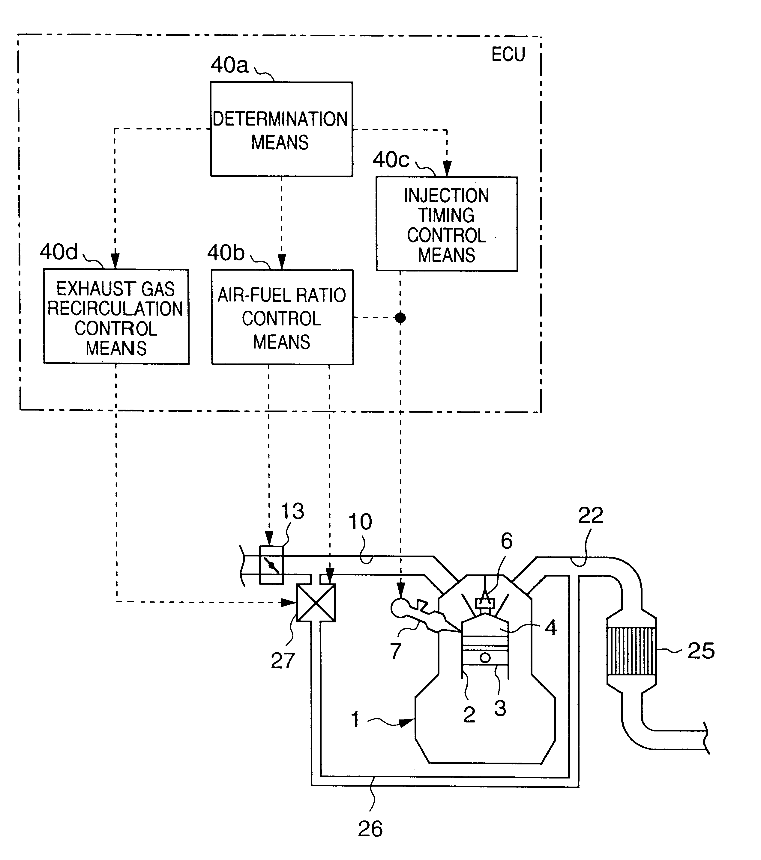
The effects of this embodiment will be explained below.

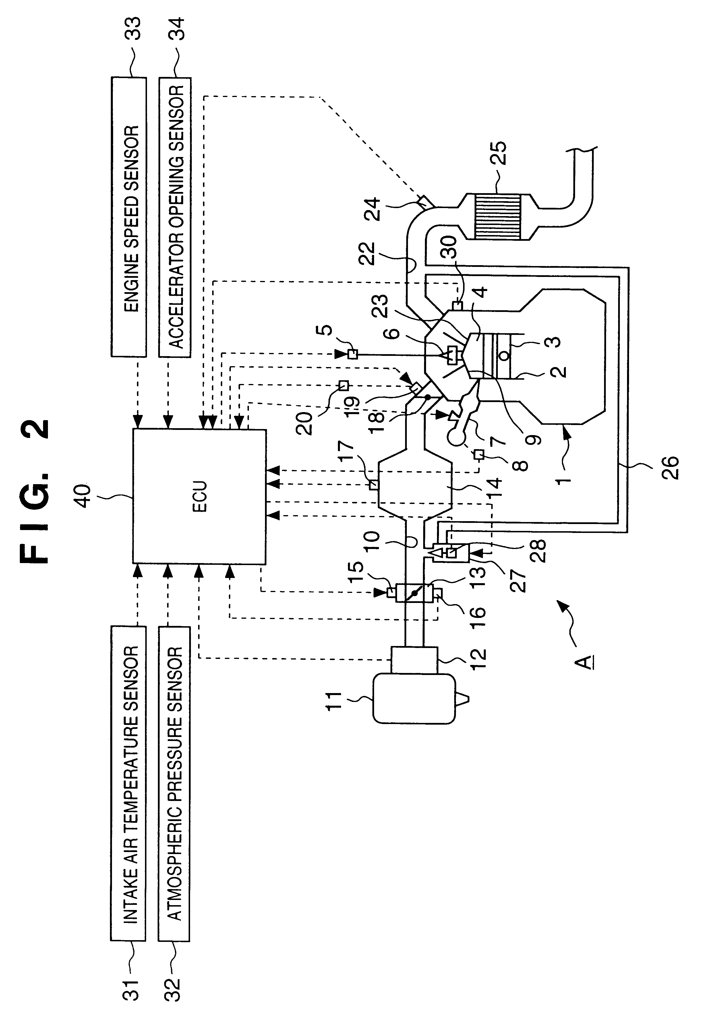
The engine 1 of this embodiment runs in the stratified combustion mode for steady combustion in a low-load range, and NOx in exhaust gas in an excess oxygen atmosphere is adsorbed and removed by the catalyst 25 at that time. When the accumulated value Tlean of the lean combustion time has exceeded the first set value T1, the forced rich flag F is turned on (F=1), and control for releasing NOx is done, as shown in steps SA15 to SA17 in the flow chart in FIG. 6.

More specifically, the total fuel injection quantity is corrected to increase, and the intake air amount is decreased by controlling the throttle valve 13 and EGR control, thus controlling the air-fuel ratio of the combustion chamber 4 of the engine 1 to fall within the range of .lambda.=1 to 1.1.

At the same time, the air-fuel mixture in the combustion chamber 4 of the engine 1 is weakly stratified by divided injection of fuel. More specifically, fuel leading injected by t...


PUM


Abstract

Upon refreshing a catalyst (25) in steps SA2 to SA6, the air-fuel ratio of each combustion chamber (4) of an engine (1) is dither-controlled to periodically vary to the rich and lean sides of a target value (A / F=15 to 16) in steps SA16 and SA17. In step SA15, an injector (7) divisionally injects fuel in two injections within the period from the intake stroke to the compression stroke of each cylinder, thus accomplishing weakly stratified combustion. In step SA18, the opening of an EGR valve (27) is controlled to recirculate a large amount of exhaust gas to an intake path (10) so as to achieve around 40% EGR ratio.

Description

1. Field of the InventionThe present invention relates to a control apparatus for a spark ignition type direct injection engine, which can remove nitrogen oxides (NOx) in exhaust gas even at lean air-fuel ratios by inserting an NOx adsorbing catalyst that adsorbs NOx in exhaust gas in an excess oxygen atmosphere into the exhaust path of the engine.2. Description of the Related ArtConventionally, as for a control apparatus for an engine of this type, the following control technique is known. That is, the air-fuel ratio of a combustion chamber is controlled to be a predetermined lean state (e.g., A / F.gtoreq.20) to improve fuel economy, and NOx in exhaust gas that has become an excess oxygen atmosphere at that time is adsorbed and removed by an NOx adsorbing catalyst. Before the adsorbed NOx amount of that NOx adsorbing catalyst becomes excessive and the adsorption performance drops, the air-fuel ratio of the combustion chamber of the engine is switched to a rich one substantially equa...

Claims


Application Information

Patent Timeline
IPC IPC(8): F02D41/14F02D21/00F02D21/08F02D41/30F02D41/02F02D41/40F01N3/08F02B75/12F02B75/00F02M25/07F02D41/34
CPCF01N3/0842F02D41/005F02D41/0275F02D41/1408F02D41/3023F02D41/402F02B2075/125F02D2250/36Y02T10/44Y02T10/123Y02T10/47Y02T10/12Y02T10/40
Inventor MAMIYA, KIYOTAKAIMADA, MICHIHIROYAMAUCHI, TAKEOTETSUNO, MASAYUKI
Owner MAZDA MOTOR CORP
Why Eureka
Try Eureka