
Multicarrier communication system and method for peak power control

a communication system and multi-carrier technology, applied in multiplex communication, orthogonal multiplex, baseband system details, etc., can solve the problem of linear (and consequently inefficient) transmit amplifier for amplification of this composite signal envelop

Inactive Publication Date: 2001-10-23
HEWLETT-PACKARD ENTERPRISE DEV LP +1
View PDF13 Cites 82 Cited by
  • Summary
  • Abstract
  • Description
  • Claims
  • Application Information

AI Technical Summary

Benefits of technology

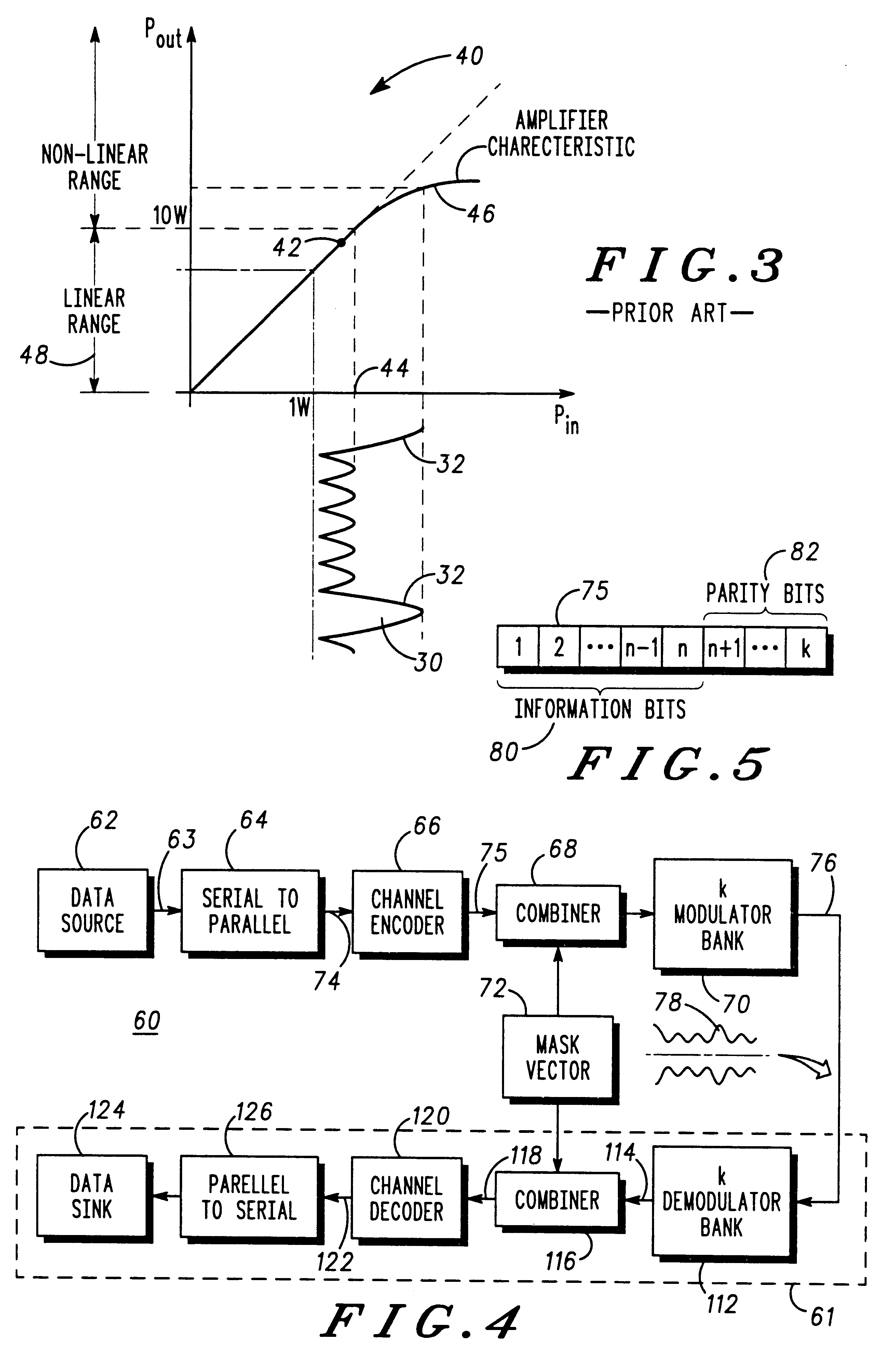
Multicarrier transmission schemes, such as OFDM, have been proposed for many different types of communication system, including Digital Audio Broadcasting (DAB) and broadband wireless Local Area Networks (LANs). The advantage of such schemes is that unlimited transmission rates are theoretically possible in highly time dispersive channels that arise from a summation of multiple delayed, attenuated and phase-shifted paths for a signal, and which therefore display a distorted characteristic. Unfortunately, the composite signal envelope produced by OFDM exhibits a high PMEPR (which term is also commonly referred to as "the crest factor"). Moreover, in order to mitigate against the effects of distortion and spectral spreading (e.g. adjacent channel splatter) in multicarrier systems, a linear (and consequently inefficient) transmit amplifier is required for amplification of this composite signal envelope.
The present invention advantageously provides a mechanism which can achieve significant improvements in PMEPR by encoding the transmitted sequence in such a way as to avoid excessive PEPs.

Problems solved by technology

Unfortunately, the composite signal envelope produced by OFDM exhibits a high PMEPR (which term is also commonly referred to as "the crest factor").
Moreover, in order to mitigate against the effects of distortion and spectral spreading (e.g. adjacent channel splatter) in multicarrier systems, a linear (and consequently inefficient) transmit amplifier is required for amplification of this composite signal envelope.
Consequently, the selection of a multicarrier transmission scheme for a system does not currently utilize the available power range to a maximum extent.

Method used


Image

  • Multicarrier communication system and method for peak power control
  • Multicarrier communication system and method for peak power control
  • Multicarrier communication system and method for peak power control

Examples


Embodiment Construction

Referring to FIG. 1, there is shown a physical representation of the mechanism by which a prior art time dispersive channel is formed. Explicitly, a data signal r(t) is subjected to a multiplicity of paths (only two of which are shown), one of which contains a time delay 10, an attenuator 12 and a phase offset 13. At a later point, the multiplicity of alternate paths are combined (as represented by summation block 14) to obtain a distorted signal R(t). As will be understood, as the bandwidth for the data signal r(t) increases, the period of the time delay affects the signal to a greater extent, and so limits the use of an available bandwidth.

FIG. 2 is a waveform diagram illustrating the formulation of a time domain signal of a prior art multicarrier system. Indeed, FIG. 2 is representative of an OFDM scheme in which the effects of the time delay are mitigated against by distributing data (not shown) amongst a plurality of frequency sub-channels 20-26 (four sub-channels in this parti...


PUM


Abstract

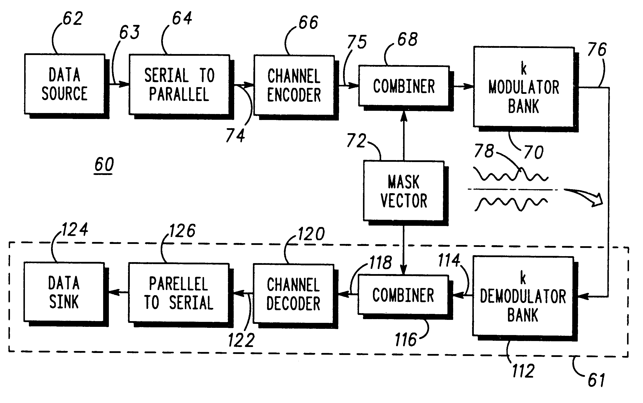
A communication device for simultaneously transmitting information on multiple sub-channels encodes information for each of the multiple sub-channels with a coding scheme to produce channel encoded information. A mask vector derived from a redundancy in the coding scheme, encodes the channel encoded information to transform the channel encoded information into codewords having pairwise Euclidean distance properties identical to those of the channel encoded information, Modulation of the sub-channels in accordance with the codewords in a modulator then produces a composite signal envelope having a peak-to-mean error power ratio (PMEPR) reduced relative to a PMEPR for correspondingly modulated channel encoded information.

Description

This invention relates, in general, to multicarrier communication systems, such as an Orthogonal Frequency Division Multiplexed (OFDM) communication system, and is particularly applicable to a mechanism for controlling the peak-to-mean envelope power ratio (PMEPR) for transmissions in such systems.SUMMARY OF THE PRIOR ARTMulticarrier transmission schemes, such as OFDM, have been proposed for many different types of communication system, including Digital Audio Broadcasting (DAB) and broadband wireless Local Area Networks (LANs). The advantage of such schemes is that unlimited transmission rates are theoretically possible in highly time dispersive channels that arise from a summation of multiple delayed, attenuated and phase-shifted paths for a signal, and which therefore display a distorted characteristic. Unfortunately, the composite signal envelope produced by OFDM exhibits a high PMEPR (which term is also commonly referred to as "the crest factor"). Moreover, in order to mitigate...

Claims


Application Information

Patent Timeline
IPC IPC(8): H04L27/26H04L27/00H04J11/00
CPCH04L27/2602H04L27/2617
Inventor JONES, ALANWILKINSON, TIMOTHY ALAN
Owner HEWLETT-PACKARD ENTERPRISE DEV LP
Learn More