Motion control methodology for a high-speed inserting machine or other mailing apparatus

Inactive Publication Date: 2001-10-09
DMT SOLUTIONS GLOBAL CORP
View PDF3 Cites 6 Cited by
  • Summary
  • Abstract
  • Description
  • Claims
  • Application Information

AI Technical Summary

Problems solved by technology

On occasion, however, a sheet in a sheet handling device will slip so that the motion of the axis does not necessarily indicate the motion of a sheet (or envelope).

Method used


Image

  • Motion control methodology for a high-speed inserting machine or other mailing apparatus
  • Motion control methodology for a high-speed inserting machine or other mailing apparatus
  • Motion control methodology for a high-speed inserting machine or other mailing apparatus

Examples


Embodiment Construction

The present invention will be described after first describing a mailing apparatus, namely a thermal postage meter, for which the methodology of the present invention could be used to generate motion profiles. The illustration afforded by the reference to a thermal postage meter is to be understood as simply one kind of application which the methodology of the present invention could be applied to determine the motion profile. The methodology of the present invention is intended for any kind of mailing apparatus, and the advantage of applying the present methodology increases as the complexity of the mailing apparatus increases, so that its application to a high-speed inserting machine, for example, is especially beneficial.

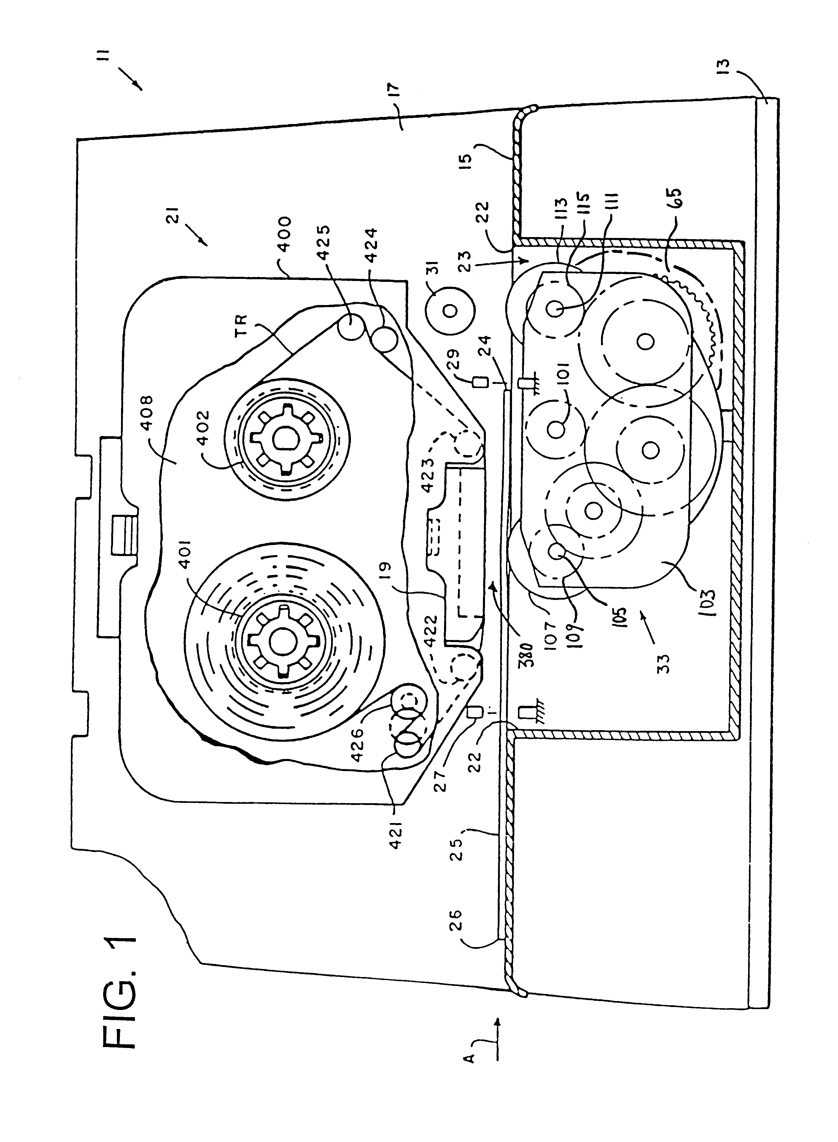
Referring now to FIG. 1, a thermal postage meter 11 includes a base 13 and a substantially vertical registration wall 17. The registration wall 17 and the base 13 are rigid structures, each providing a suitable framework for mounting and supporting various other ...


PUM


Abstract

A methodology for generating a motion profile for an axis of a motor in a mailing apparatus, the linear or angular motion of the motor axis imparting a motion to a sheet or envelope being conveyed by the mailing apparatus. The methodology includes four processes for generating a segment of a motion profile, depending on whether, for the segment, absolute positional synchronism (of the motor axis to be controlled relative to another motor axis) is needed, or whether a so-called quick step is needed, i.e. a change in velocity corresponding to acceleration that varies during the step. The processes include: forward integration, given the jerk (acceleration per unit time) and starting acceleration as well as initial values of position and velocity; non-parabolic displacement mapping (sometimes called electronic gearing) relating the motion of the axis to be controlled to the motion of another axis where the function expressing the mapping is not parabolic in the commanded or actual position of the other axis; integration based on a velocity equation that is parabolic in time; and a parabolic displacement mapping, i.e. a displacement mapping using a function that is parabolic in the actual or commanded position of a reference axis.

Description

The present invention pertains to the field of sheet feeding. More particularly, the present invention pertains to controlling the motion of sheets through a sheet handling device, such as a mailing machine, a postage meter, an envelope printer or inserter, and including a high-speed inserter.BACKGROUND OF INVENTIONA typical sheet or envelope handling device includes various structures, motors and sensors. For example, a typical envelope handling device includes an envelope feeding structure for feeding an envelope or a batch of envelopes in singular fashion in a downstream path of travel to a work station. Typical envelope handling devices employ ejection rollers or ejection belts operating at a constant speed, or at some speed that varies as a function of time, speeds chosen so as to avoid envelope collisions and noise, and also to avoid so-called bounce-back from a wall when an envelope strikes a wall designed to stop its forward travel and cause it to drop onto the top of a stac...

Claims


Application Information

Patent Timeline
IPC IPC(8): B65H5/34G07B17/00
CPCB65H5/34G07B17/00467B65H2511/212B65H2511/514B65H2513/20B65H2513/51B65H2557/24B65H2701/1916G07B2017/0054B65H2220/02B65H2220/11B65H2220/01
Inventor SALAZAR, EDILBERTO I.SUSSMEIER, JOHN W.
Owner DMT SOLUTIONS GLOBAL CORP
Why Eureka
Try Eureka