Isolated support for a rear suspension component 1

a rear suspension and support technology, applied in the field of rear frame structure for rear suspension components, can solve the problems of not being able to the suspension strut tower is not readily adjustable relative to any support for establishing a high degree of spacing, and the prior construction does not provide the isolation of the suspension component from the strut tower

Inactive Publication Date: 2001-09-25
FCA US
View PDF11 Cites 53 Cited by
  • Summary
  • Abstract
  • Description
  • Claims
  • Application Information

AI Technical Summary

Benefits of technology

This invention's closed loop vehicle framing structure effectively counters bending moments imparted through the strut towers. The rigidity of the resultant structure permits the suspension components to more effectively operate in dissipating or converting energy imparted from road irregularities which tend to induce vibrations which otherwise would travel into the vehicle passenger compartment. More particularly, the closed loop support system of this invention completes an internal load path extending around the closed perimeter of the framing structure so that the suspension mounting points are sufficiently stiff wherein road induced vibrations are substantially dissipated by the suspension. Accordingly, this invention minimizes transmittal of vibration and noise into the interior compartments of the vehicle.
The above described framing and isolating attachment structure for mounting suspension components such as a MacPherson strut also permits the strut's coil spring and associated shock absorber to function with greater efficiency so as to substantially improve the level of vibrations and noise that are dissipated but also to decrease any degree of directly transmitted vibrations and noise from the MacPherson strut component to the vehicle framing so as not to adversely affect occupants or equipment in the associated vehicle.
This framing structure also readily adapts to the addition of a pass-through feature between the rear of the passenger compartment and the luggage / cargo space or trunk. Thus, a fold-down trunk access panel or the like can be incorporated so that elongated objects such as skis can be extended from the trunk into the passenger compartment and transported within the vehicle. Prior vehicle rear framing includes a relatively continuous body structure behind the rear seat back which inhibits addition of an effective pass-through structure. The previous trunk blocking structure is eliminated with the provision of the improved closed loop framing structure which even more importantly also provides increased structural rigidity that improves the support of the back of the rear seat of the vehicle as well as the suspension components.
By attachment of accurately aligned strut towers to the upper and lower cross beams, a generally ring-shaped or closed loop framing structure is provided which is extremely rigid. This construction results in the two suspension strut towers to be very accurately positioned with respect to each other and with respect to the beam members. A framing structure is created that is sufficiently rigid to effectively support suspension components such as shock absorbers and springs. Resultantly, this improves the efficiency of the suspension springs and shock absorbers in dissipating road vibrations and any transmission of vibrations and noise into the interior compartments of the vehicle are greatly reduced by the strut isolation structure.

Problems solved by technology

With this construction, the suspension strut towers are designed to support rear wheel suspension components but are not readily adjustable relative to any supports for establishing a high degree of accuracy in spacing or parallelism.
More particularly, the prior constructions do not provide the isolation of the suspension component from the strut tower and framing structure as in the subject embodiment.
Resultantly, the suspension springs and shock absorbers cannot operate with high efficiency to dampen road caused vibrations while still isolating the vehicle body from feedback from the suspension components.
This isolation arrangement greatly inhibits transmission of road related vibrations to the vehicle framing from the suspension component.

Method used


Image

  • Isolated support for a rear suspension component 1
  • Isolated support for a rear suspension component 1
  • Isolated support for a rear suspension component 1

Examples


Embodiment Construction

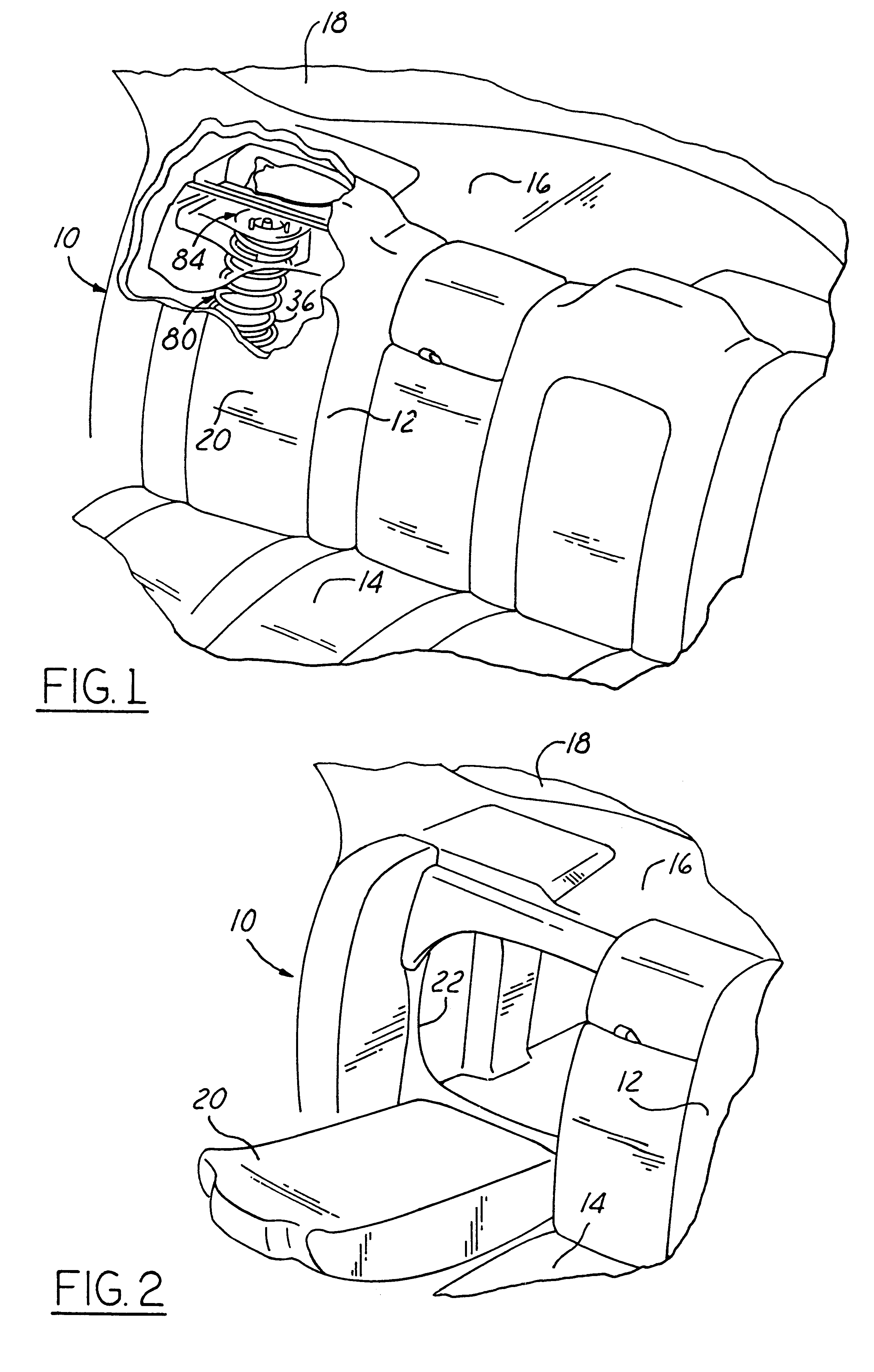
Turning now in greater detail to the drawings, FIG. 1 shows a portion of the interior of an automotive vehicle and more particularly the rear seating area 10 having a seat assembly including a seat back 12 and seat cushion 14. Above and to the rear of the vehicle is a generally horizontal panel 16 at the base of a rear window or back light 18. As previously mentioned, the subject framing system allows for a pass-through feature from the passenger compartment to the trunk. In this regard, a portion 20 of the seat back is mounted for pivotal movement from a closed position shown in FIG. 1 to an opened position shown in FIG. 2. In the opened position, the pivotal portion 20 moves out of the way to uncover an access opening 22 which extends or opens into the trunk. The pivotal portion 20 can be selectively opened and folded down for communication between the vehicle trunk and the passenger compartment so that long objects such as skis, can be easily loaded and carried in the vehicle.

FIG...


PUM


Abstract

A framing structure for support of the rear suspension components of an automotive which includes a pair of generally vertically oriented suspension strut towers spaced laterally with respect to the vehicle and with each strut tower fixedly attached at lower end portions to a lower cross beam and fixedly attached at upper end portions to an upper cross beam and having an isolating structure at the upper end portion of each strut tower to which the upper end portion of a rear suspension component such as a shock absorber or a MacPherson suspension strut is attached in a manner isolating the suspension component from the strut tower and upper cross beam.

Description

1. Field of the InventionThis invention concerns framing for a vehicle, and more particularly, to an improved rear frame structure for rear suspension components, primarily MacPherson type strut components which combine a shock absorber and a coil spring in a unitary assembly, the lower end portion of the strut component is operatively attached to a rear wheel support or spindle and the upper end of which is operably attached to the vehicle framing structure. The framing structure incorporates a pair of vertically oriented strut support towers spaced from one another laterally across the vehicle. A pair of laterally extending upper and lower cross beams extend between and are attached to the strut towers wherein a high degree of accuracy in tower spacing and alignment contributes to very accurate positioning thereof, particularly of the tower's upper end portions which are operably attached to the associated MacPherson suspension components. The subject arrangement provides an isola...

Claims


Application Information

Patent Timeline
IPC IPC(8): B60G15/06B60G15/00B62D25/08F16F9/54
CPCB60G15/063B60G15/067F16F9/54B62D25/088B60G2200/46B60G2202/312B60G2204/124B60G2204/1242B60G2204/41B60G2204/43B60G2204/44B60G2204/61B60G2204/128
Inventor ROBBINS, NORMAN B.CORPORON, MAX A.
Owner FCA US
Why Eureka
Try Eureka