
Vehicle air-conditioning system with independent left/right temperature control during maximum cooling

Inactive Publication Date: 2001-09-25
DENSO CORP
View PDF13 Cites 55 Cited by
  • Summary
  • Abstract
  • Description
  • Claims
  • Application Information

AI Technical Summary

Benefits of technology

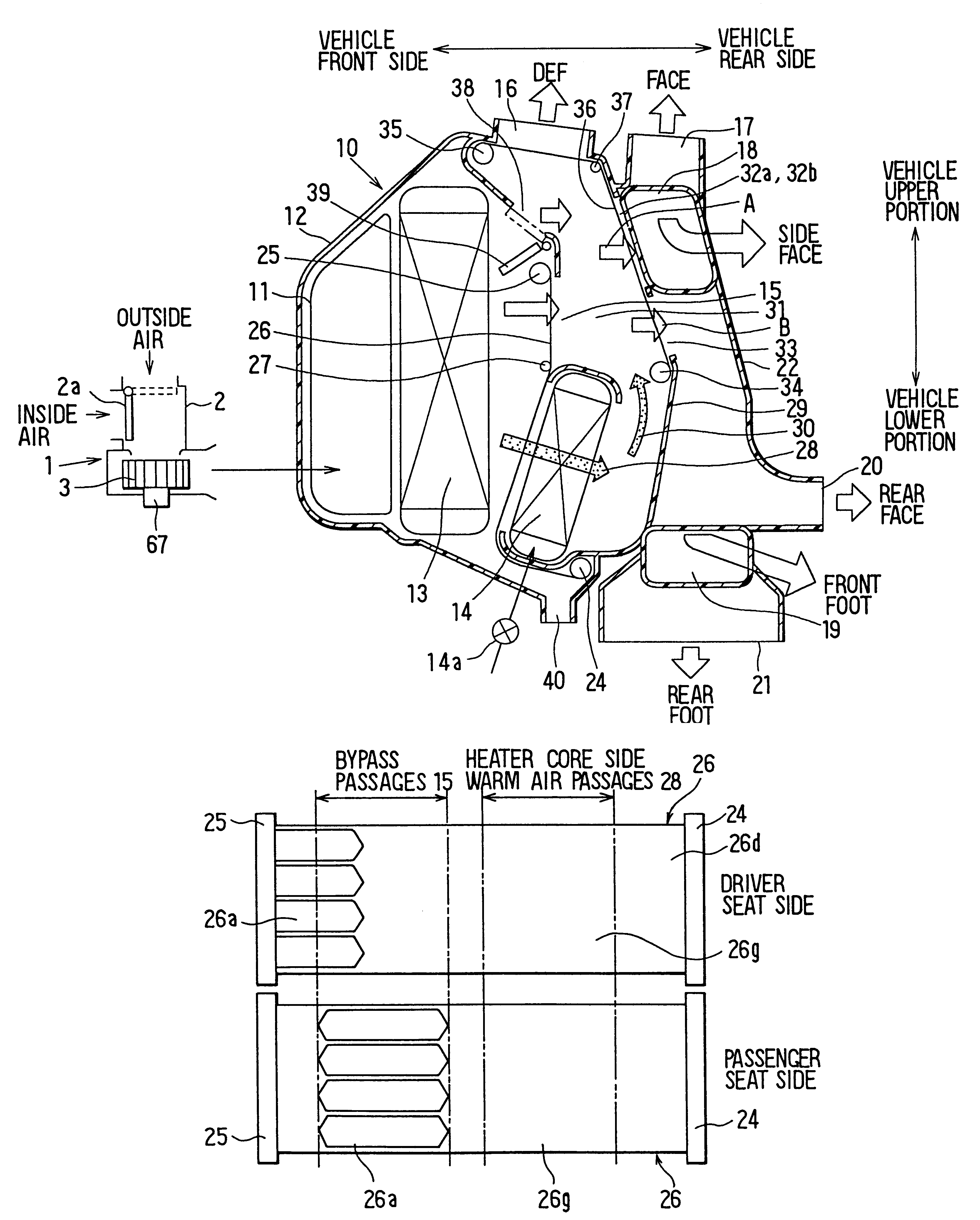
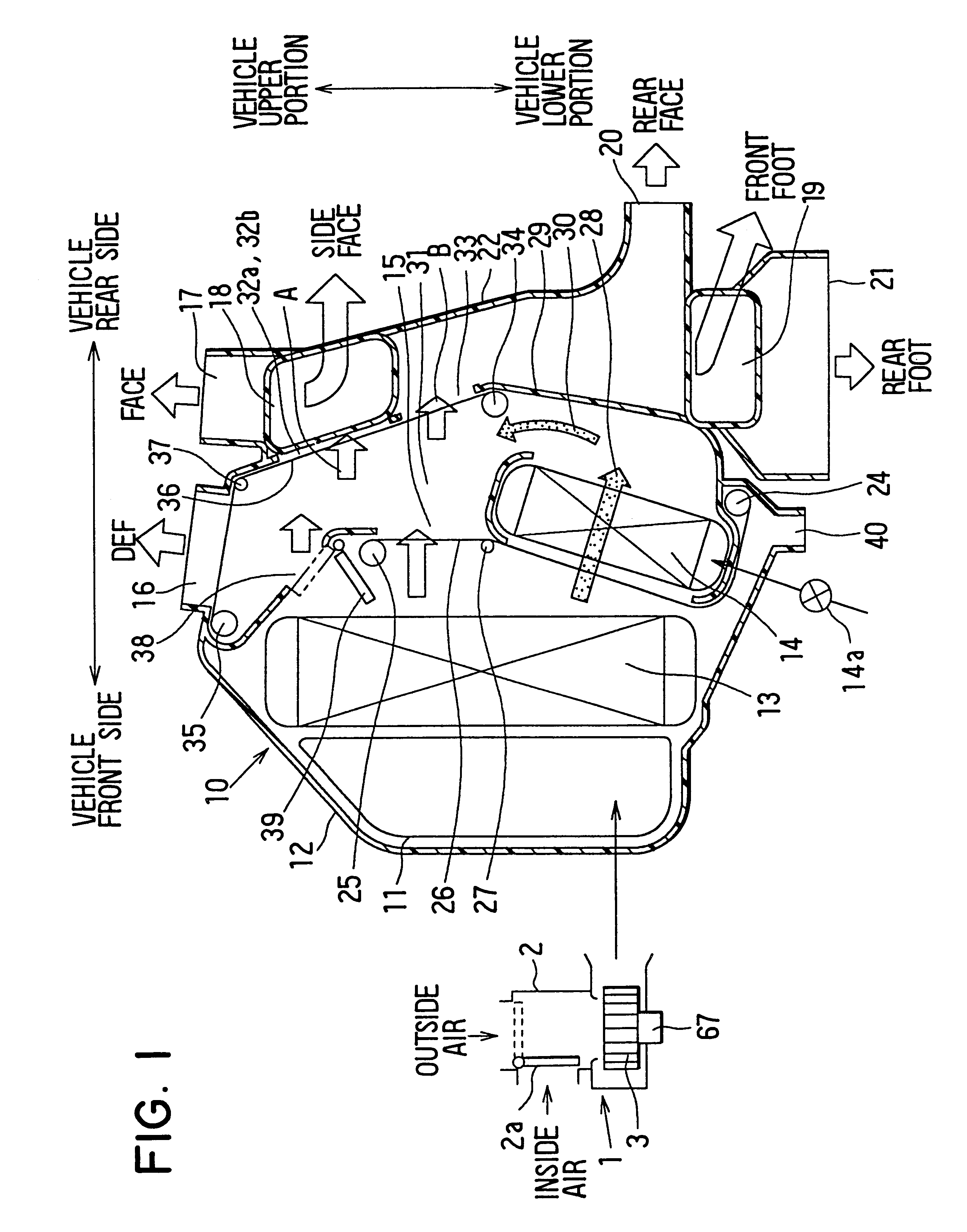
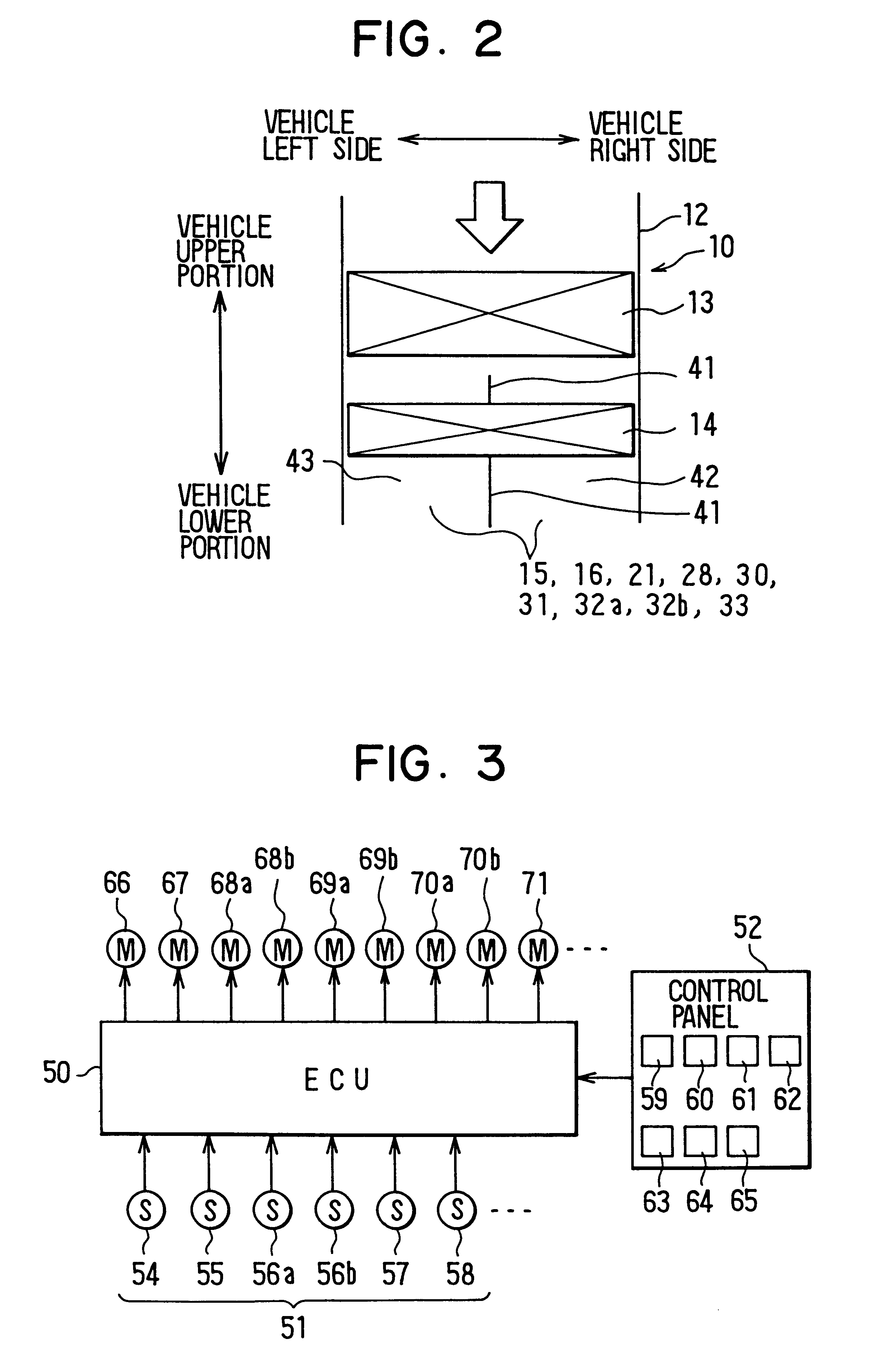
As a result, cool air flow can be increased on the side having the increased heat load by increasing the delivery flow of the blower, while the amount of cool air blown out to the side exhibiting little or no temperature increase can be prevented from excessively increasing through reduction of the open area of the respective ventilation path.
Therefore, even when the heat loads of the left and right sides of the vehicle are different due to unbalanced solar radiation or the like at a time of maximum cooling, the left-right flow distribution can be controlled in correspondence with the left and right heat loads, and both left and right side occupants can be satisfactorily cooled.

Problems solved by technology

When there is an unbalanced incidence of solar radiation on a vehicle, such as when a passenger seat side (left side), is exposed to solar radiation while a driver seat side (right side) is not, a temperature difference due to the radiation arises between the two sides.
However, in a vehicle air-conditioning system of the kind mentioned above, the left and right side outlet temperatures cannot be varied by changing the operating position of the air-mixing door when the air-mixing door has already been operated to its maximum cooling position.
Even though there is no specific description of a relationship between blower flow and position control of the left and right film type air-mixing doors at times of maximum cooling, certain cooling limitations are present in the above-described system.
As a result, the driver side is excessively cooled.

Method used


Image

  • Vehicle air-conditioning system with independent left/right temperature control during maximum cooling
  • Vehicle air-conditioning system with independent left/right temperature control during maximum cooling
  • Vehicle air-conditioning system with independent left/right temperature control during maximum cooling

Examples


Embodiment Construction

)

In the preferred embodiments described above, cases wherein the side face openings 32b connecting with the side face outlet port 18 open directly onto the air-mixing chamber 31 without the ventilation mode switching film member 36 coming therebetween were described. However, the side face openings 32b may of course alternatively be made to open onto the air-mixing chamber 31 in a full ventilation mode by way of an opening provided in the ventilation mode switching film member 36.

By adding an opening to the ventilation mode switching film member 36 for opening the side face openings 32b in such a manner, in the fourth preferred embodiment described above, the open areas of the center face opening 32a and the side face openings 32b can both be reduced with the ventilation mode switching film member 36 on the side having the higher TAO to suppress the cool air blowout flows from both the center face outlet and the side face outlets. Thus it is possible using the ventilation mode switc...


PUM


Abstract

A vehicle air-conditioning system that independently controls left-right air flow distribution in correspondence with left and right heat loads during a maximum cooling mode. In the system, blowout air flow is increased when driver seat side and passenger seat side air-mixing film members are both positioned in a maximum cooling position, and the heat load has risen in only one of a driver seat side space and a passenger seat side space in a passenger compartment. Further, each respective film member is operated to fully open a cool air bypass passage on the side on which the heat load has risen and the respective film member corresponding to the side on which the heat load has not risen significantly is operated to reduce the open area of the cool air bypass passage. At the same time, fan speed is increased to increase the air blow amount.

Description

The present invention is related to, and claims priority from, Japanese Patent Application Hei. 10-60188.1. Field of the InventionThis invention relates to a vehicle air-conditioning system capable of independently controlling left and right outlet air temperatures by adjusting flow proportions of warm and cool air flows, and particularly to a system capable of independently controlling the cooling of both left and right side occupants at times of maximum cooling by controlling a left-right air flow distribution.2. Description of the Related ArtIn conventional air-mixing type vehicle air-conditioning systems, an air-mixing door is operated at times of maximum cooling to a position in which it fully opens a cool air bypass passage and fully closes an air inflow path to a heat exchanger for heating. When there is an unbalanced incidence of solar radiation on a vehicle, such as when a passenger seat side (left side), is exposed to solar radiation while a driver seat side (right side) i...

Claims


Application Information

Patent Timeline
IPC IPC(8): B60H1/00
CPCB60H1/00064B60H2001/00135Y10S251/901B60H2001/00192B60H2001/00171
Inventor UEMURA, YUKIONATSUME, TAKUYASHIKATA, KAZUSHI
Owner DENSO CORP
Learn More