
Residential motorized sliding door assembly

Inactive Publication Date: 2001-09-18
AUTOGLIDE
View PDF21 Cites 88 Cited by
  • Summary
  • Abstract
  • Description
  • Claims
  • Application Information

AI Technical Summary

Benefits of technology

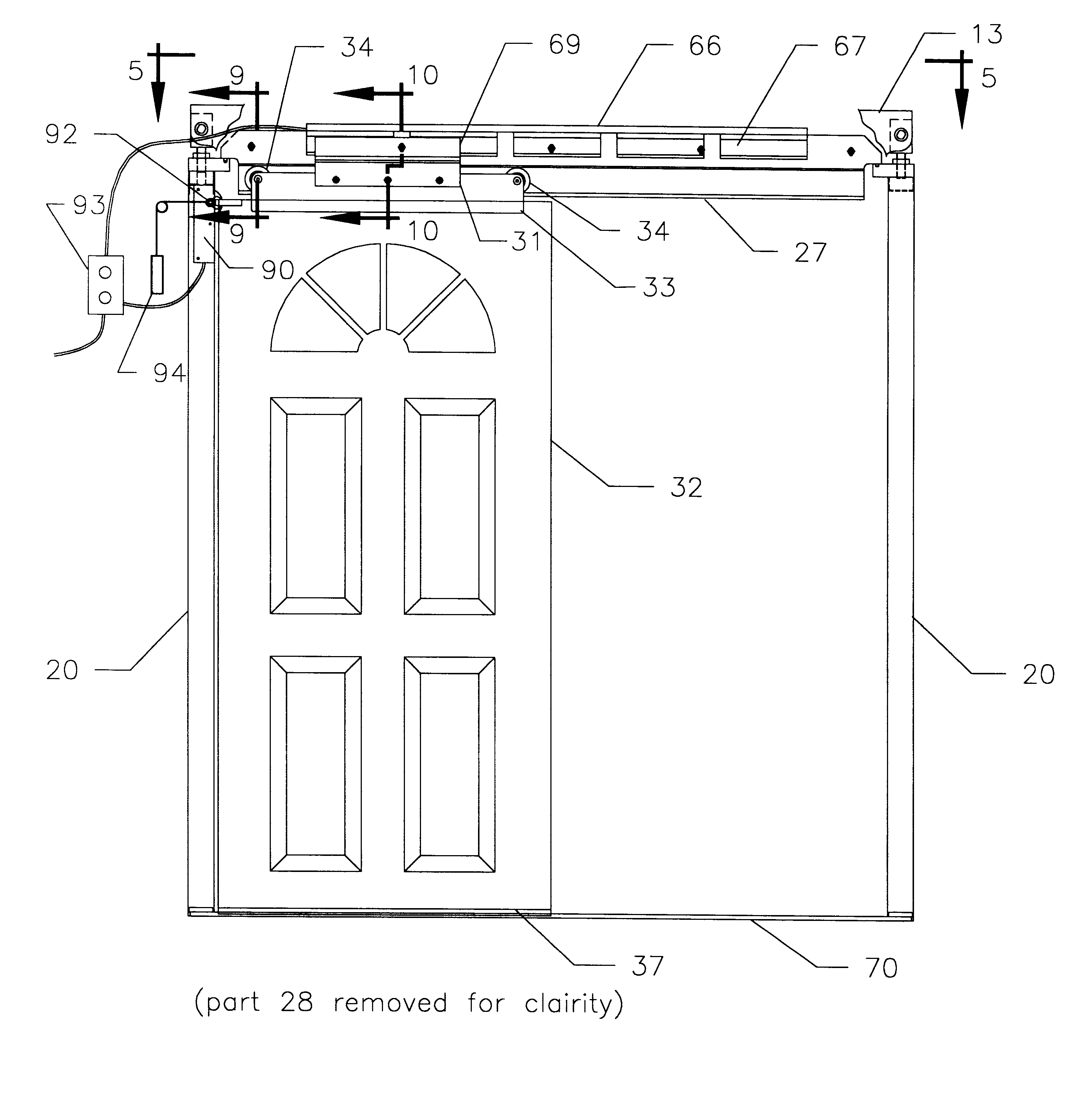
Also located inside the header is a low profile motor coupled to the sliding door that selectively moves the sliding door longitudinally along the track rail. In the preferred embodiment, the motor is a brush-less, linear motor with no moving parts to reduce sound and lower service requirements. The motor is electrically connected to an electricity source and a switch means that allows the user to selectively open and close the sliding door.
Located around the inside and outside surfaces of the support frame and the fixed panels is a sealing frame assembly that beautifies the assembly and creates a secure, weather-resistant barrier when the sliding door is closed. An optional locking means is also provided between the sliding door and the frame assembly for additional security.

Problems solved by technology

As a result, any empty space above the door for other structures or other objects is small or non-existent.
In many residences, pocket doors are commonly constructed in non-supporting, interior walls where wall and room space is limited or when a hinged door is architecturally undesirable.
First, they are not sufficiently durable for the numerous openings entrance doors typically must endure.
Second, the limited space above the header required for doors and their reduced security and weatherproofing characteristics make them undesirable.
Third, many residence owners find manually opening and closing a sliding door more inconvenient or difficult than opening and closing a hinged door.

Method used


Image

  • Residential motorized sliding door assembly
  • Residential motorized sliding door assembly
  • Residential motorized sliding door assembly

Examples


Embodiment Construction

)

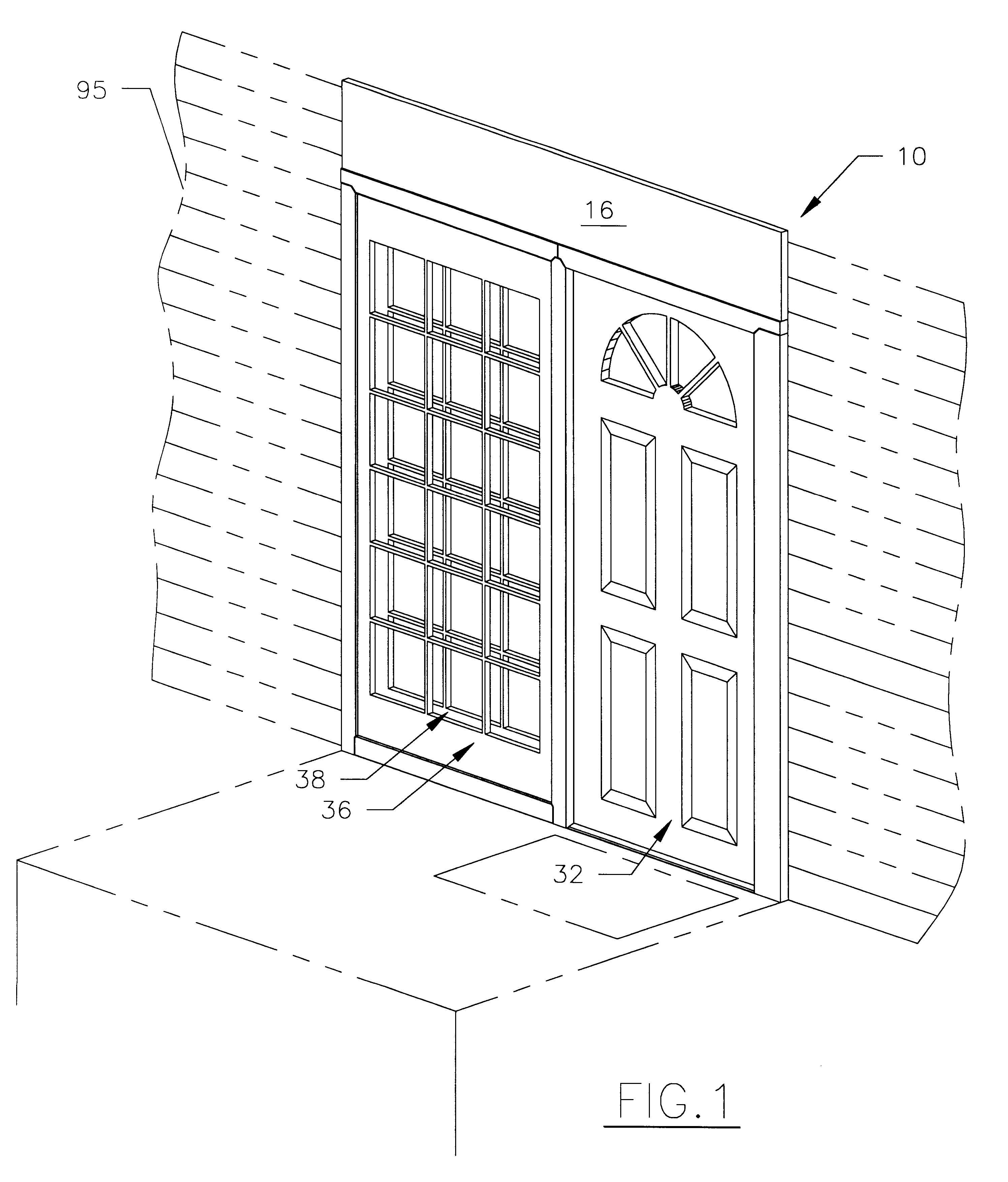
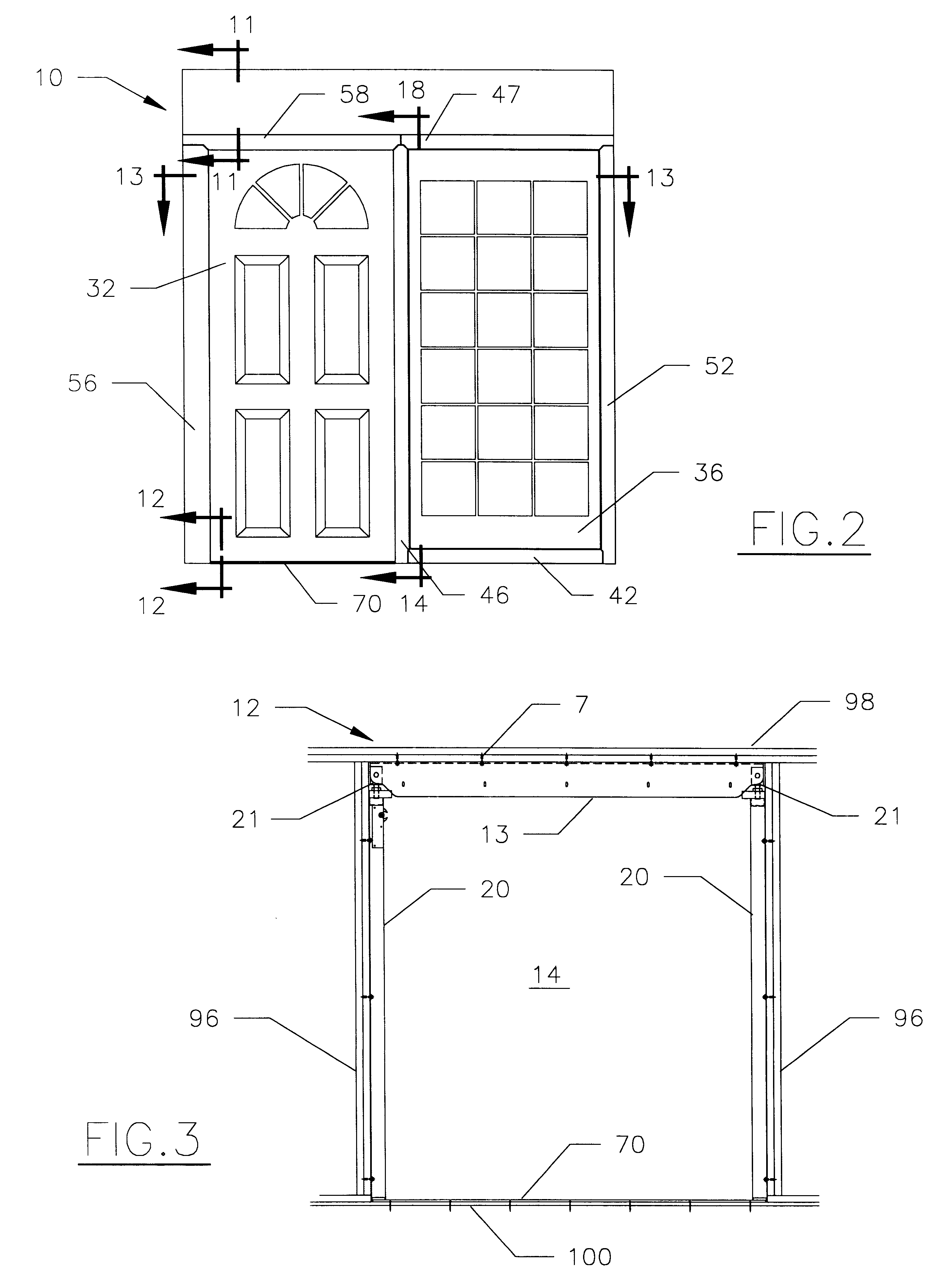
Referring to FIGS. 1-3, there is shown a motorized sliding door assembly 10 that includes ceiling load supporting, security, and weather-resistant features that enable it to be used in an exterior or interior wall of a building. The assembly 10 also is designed specifically for a 2.times.4 stud frame wall 96 on a building 95 thereby enabling it to be used in new construction or retro-fitted into an existing building. The assembly 10 includes a sliding door 32 which slides horizontally inside a strong, durable support frame 12. Located on one side of the support frame are two fixed panels 36, 38, that are spaced-apart to create a pocket in which the sliding door 32 extends when opening.

As shown in FIG. 3, the support frame 12 is assembled inside an opening 97 formed in the wall 96. The support frame 12 includes a load bearing header 13 supported at its opposite ends by two vertically aligned side posts 20. The lower end of each side post 20 is securely attached to the opposite ends ...


PUM


Abstract

A motorized sliding door assembly including a sliding door that slides longitudinally inside an outer support frame assembled in a standard 2x4 stud wall opening in a building. The support frame includes a load-bearing header located horizontally between two vertical posts and opposite a lower threshold. Jack screws are placed between the ends of the header and the vertical posts which enable the position of the header to be adjusted relative to the vertical posts and against the ceiling plate. Located inside the header is a longitudinally aligned track rail that rests on top of the vertical posts over which the sliding door moves. Located inside the header is a linear motor. Disposed vertically inside the support frame are two parallel fixed panels that are sufficiently spaced-apart to create a pocket in which the sliding door may extend. Also provided around the support frame and fixed panels is a sealing frame assembly that creates a weather-tight seal therebetween when the sliding door is closed.

Description

1. Field of the InventionThe present invention relates to sliding door assemblies and, more particularly, to motorized sliding door assemblies designed for residences.2. Description of the Related ArtIt is widely known that, in residences, standard ceiling heights range between 90 and 96 inches and standard door heights range between 80 and 82 inches. The distance between the top of the door and the ceiling, hereinafter called the header space, ranges between 10 and 16 inches. When constructing doorways on exterior or interior support walls, a single thick piece of wood is used as a single header, or two thin pieces of wood placed side-by-side are used as a double header to support the ceiling load. As a result, any empty space above the door for other structures or other objects is small or non-existent.Many mechanical doors for residences, such as garage doors, are rated according to the number of times they are opened. For example, inexpensive garage doors are rated for 10,000 to...

Claims


Application Information

Patent Timeline
IPC IPC(8): E05F15/18E05F15/00E06B3/32E06B3/46E05D15/06E05F15/60
CPCE05F15/60E06B3/4654E05D15/063E05D15/0652E05Y2900/14
Inventor BONAR, CHRISTOPHER L.
Owner AUTOGLIDE
Learn More