Method of imaging the permeability and fluid content structure within sediment
a fluid content structure and permeability technology, applied in the field of high-precision non-destructive methods of measuring physical characteristics of sediments, can solve the problems of not providing information concerning unable to provide information regarding the spatial distribution of permeability, and limited field of study, so as to achieve accurate and clear measurement, accurate cross-sectional spatial distribution of porosity and permeability values and variations, and high-precision non-destructive
Inactive Publication Date: 2001-09-11
YAMAMOTO ENG +1
View PDF3 Cites 30 Cited by
- Summary
- Abstract
- Description
- Claims
- Application Information
AI Technical Summary
Benefits of technology
Accordingly, it is an object of the present invention to provide a highly accurate non-destructive method of measuring physical characteristics of sediments and, particularly to obtain accurate
Problems solved by technology
Imaging the permeability structure within sediments has been a challenge to exploration geophysicists for many years.
The results so far have been very limited.
However, this method has the significant disadvantage that it is very expensive and time-c
Method used
View moreImage
Smart ImageViewing Examples
Examples
 PUM
 Abstract
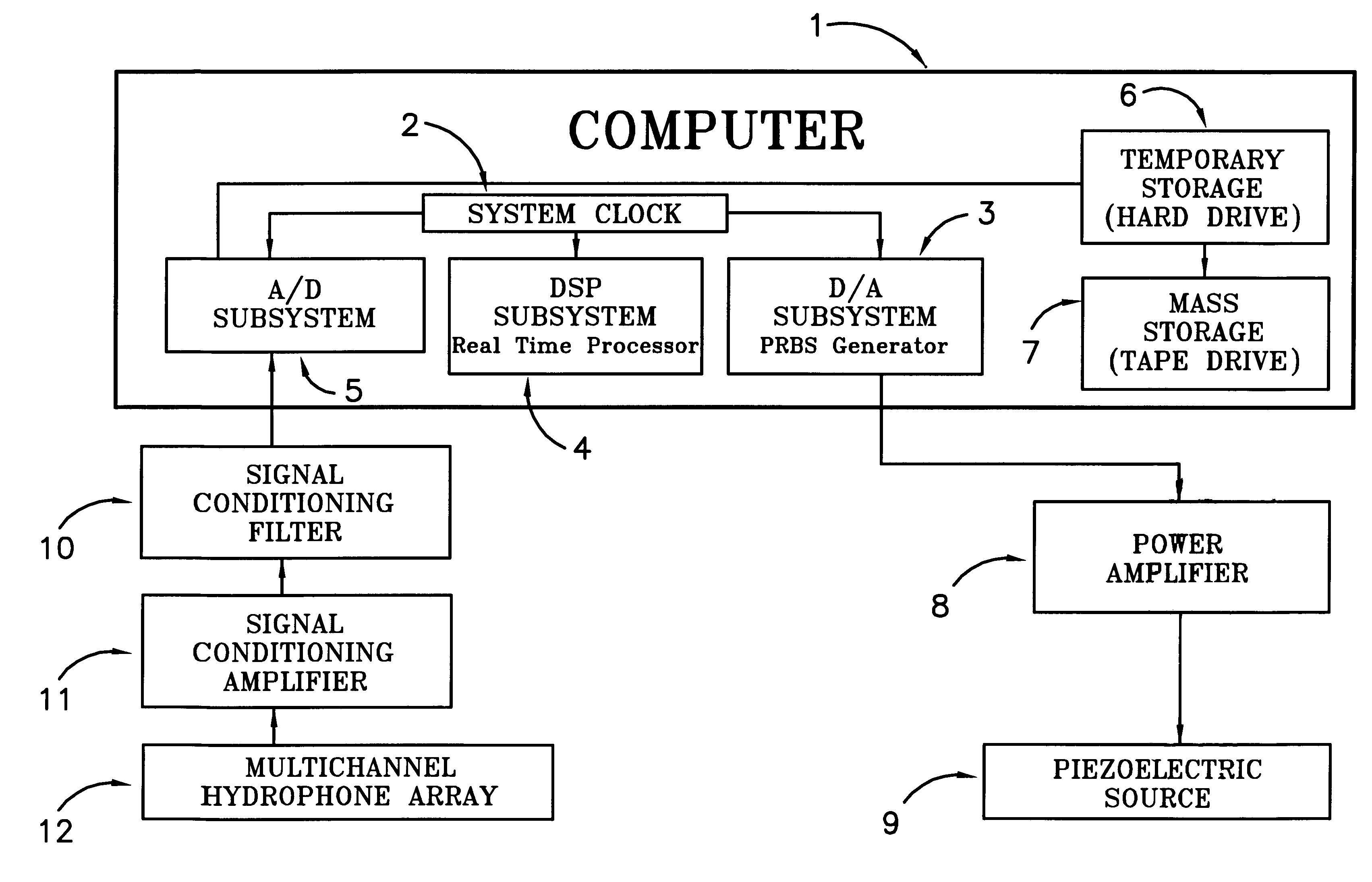
A non-destructive method of measuring physical characteristics of a medium, such as uncemented sediment, sandstone, or limestone. A pseudo-random code is generated and is used to generate a pseudo-random acoustic signal. This signal is transmitted into the medium to be measured through the use of a transducer, such as a piezoelectric element, and is received by a plurality of hydrophones. The received signal is then processed to obtain an image of its velocity and attenuation. A universal geoacoustic model of the medium for a given set of measured data is determined, and the model is solved to obtain a pair of permeability-porosity results for the medium. The one of this pair of permeability-porosity results which is correctly indicative of the physical characteristics of the medium is then determined.
Description
The present invention relates to a method of imaging the permeability and fluid content structure within geological sediments, more particularly to the use of cross-well tomography to image geological structures, and more particularly to the use of cross-well tomography to image the porosity and shear strength in geological structures.Imaging the permeability structure within sediments has been a challenge to exploration geophysicists for many years. The results so far have been very limited.In practice, perhaps the most reliable conventional method of measuring permeability within sedimental earth is through the use of a pumping test. This method requires at least two wells to pump water continuously out of one well at a constant rate and to observe the amount of change in the resulting water level of the other well. These two wells must also penetrate down to the layer of interest, and the well section above the layer of interest must be cased to isolate the layer. In such convent...
Claims
Login to View More Application Information
Patent Timeline
 IPC IPC(8): G01V1/40G01V1/42E02D1/02G01N15/08G01N29/00G01V1/28
CPCG01V1/42
Inventor YAMAMOTO, TOKUO
Owner YAMAMOTO ENG
Features
- R&D
- Intellectual Property
- Life Sciences
- Materials
- Tech Scout
- Unparalleled Data Quality
- Higher Quality Content
- 60% Fewer Hallucinations
Learn More Browse by: Latest US Patents, China's latest patents, Technical Efficacy Thesaurus, Application Domain, Technology Topic, Popular Technical Reports.
© 2025 PatSnap. All rights reserved.Legal|Privacy policy|Modern Slavery Act Transparency Statement|Sitemap|About US| Contact US: help@patsnap.com


