
Method and apparatus for detecting external cracks from within a metal tube

Inactive Publication Date: 2001-08-07
NAT TECH & ENG SOLUTIONS OF SANDIA LLC
View PDF0 Cites 68 Cited by
  • Summary
  • Abstract
  • Description
  • Claims
  • Application Information

AI Technical Summary

Problems solved by technology

Historically, and even to the present day, the major cause of boiler outages is the degradation of the steam tubes by which heat is extracted from the boiler.
Although there is deposition and corrosion upon the internal surfaces of the tubes, the principal cause of failure is by the development of exterior cracks.
Unfortunately, some cracks may not be discovered because the exterior surfaces are more or less covered by combustion or corrosion products.

Method used


Image

  • Method and apparatus for detecting external cracks from within a metal tube
  • Method and apparatus for detecting external cracks from within a metal tube
  • Method and apparatus for detecting external cracks from within a metal tube

Examples


example

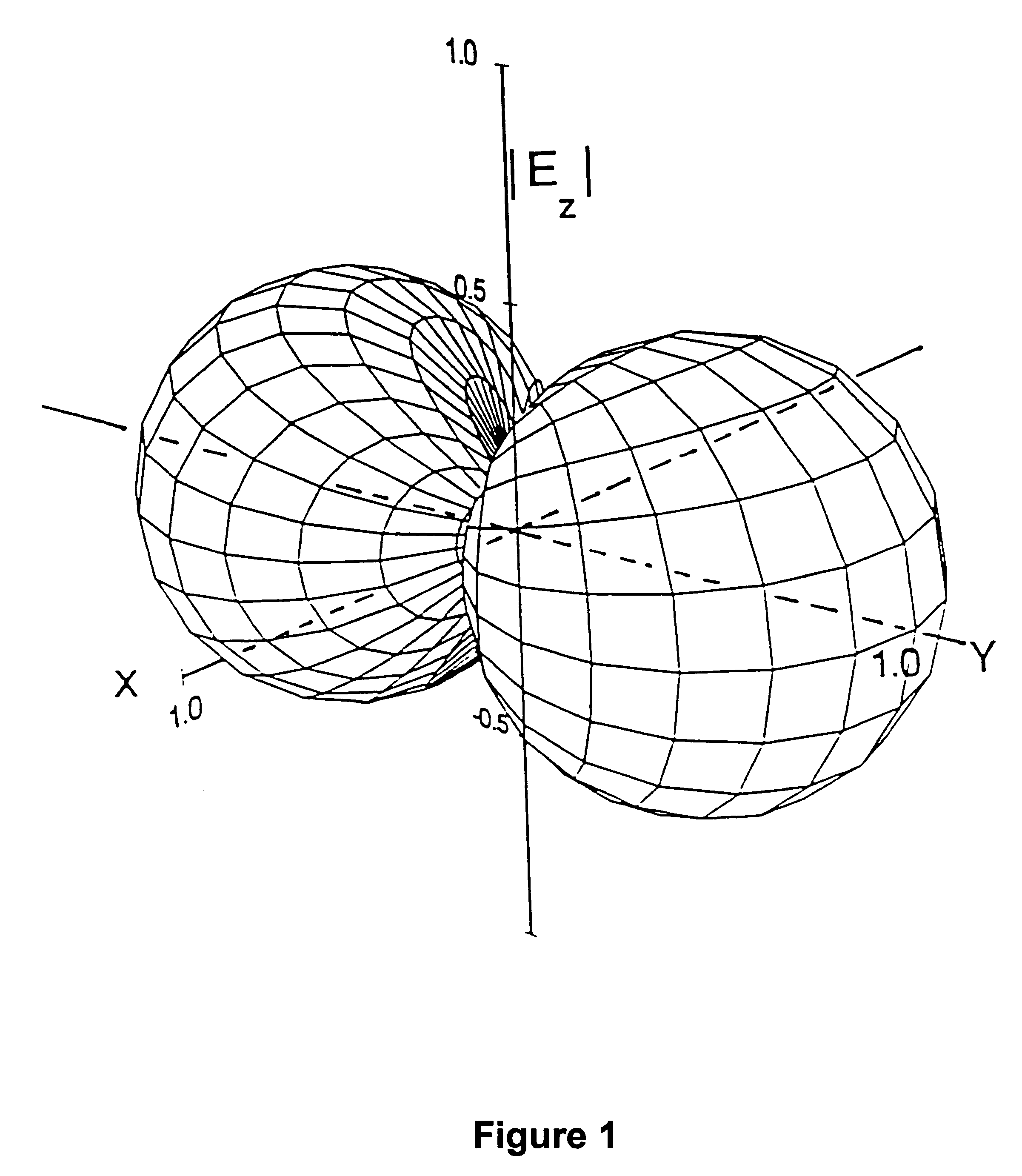
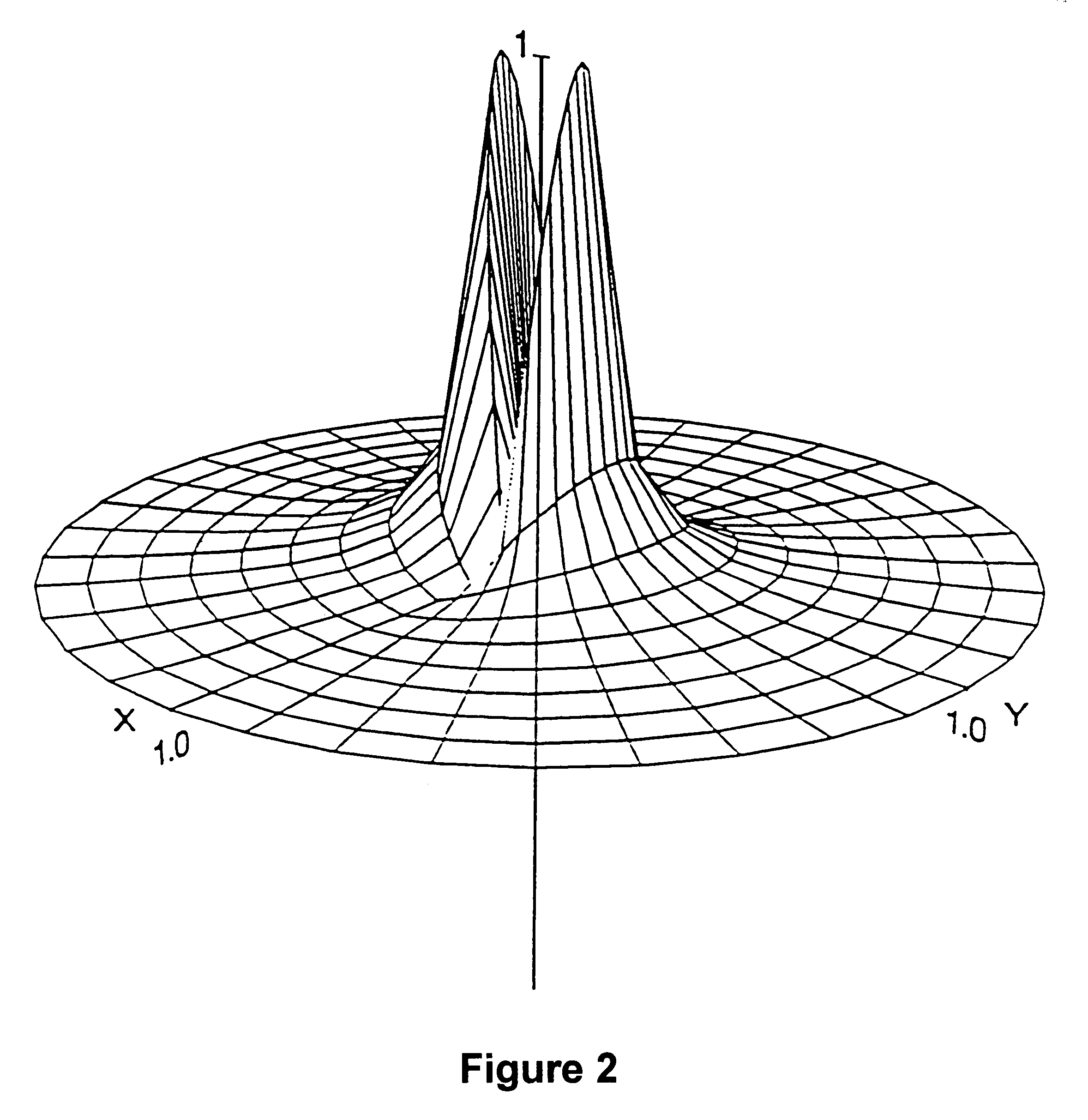
An Inconel tube with an inner diameter of 2.2 cm, a wall-thickness of 0.127 cm, and a conductivity of 8.2E5 S / m is typical of the smallest tube commonly found in boilers. The frequency of 47.88 KHz will be used to make the two-way path through the wall equal to one skindepth so that the second term in Eq.(3) becomes -8.7 dB. In the following figures, the fields will be presented as normalized surfaces in cylindrical coordinates in which radial distances are relative to the tube radius. The increments of normalized radius and polar angle will be 0.1 and 10.degree. respectively.

FIG. 2 illustrates the relative magnitude of E.sub.z in the xy-plane. The figure is dominated by the double-peaks near the z-axis. These occur because the field is computed ever more closely to the magnetic dipole located at the origin (where the graph is set to zero for display purposes). When the field along the tube wall at p=1 is examined closely, the field is seen to vary as the cosine of the polar angle r...


PUM


Abstract

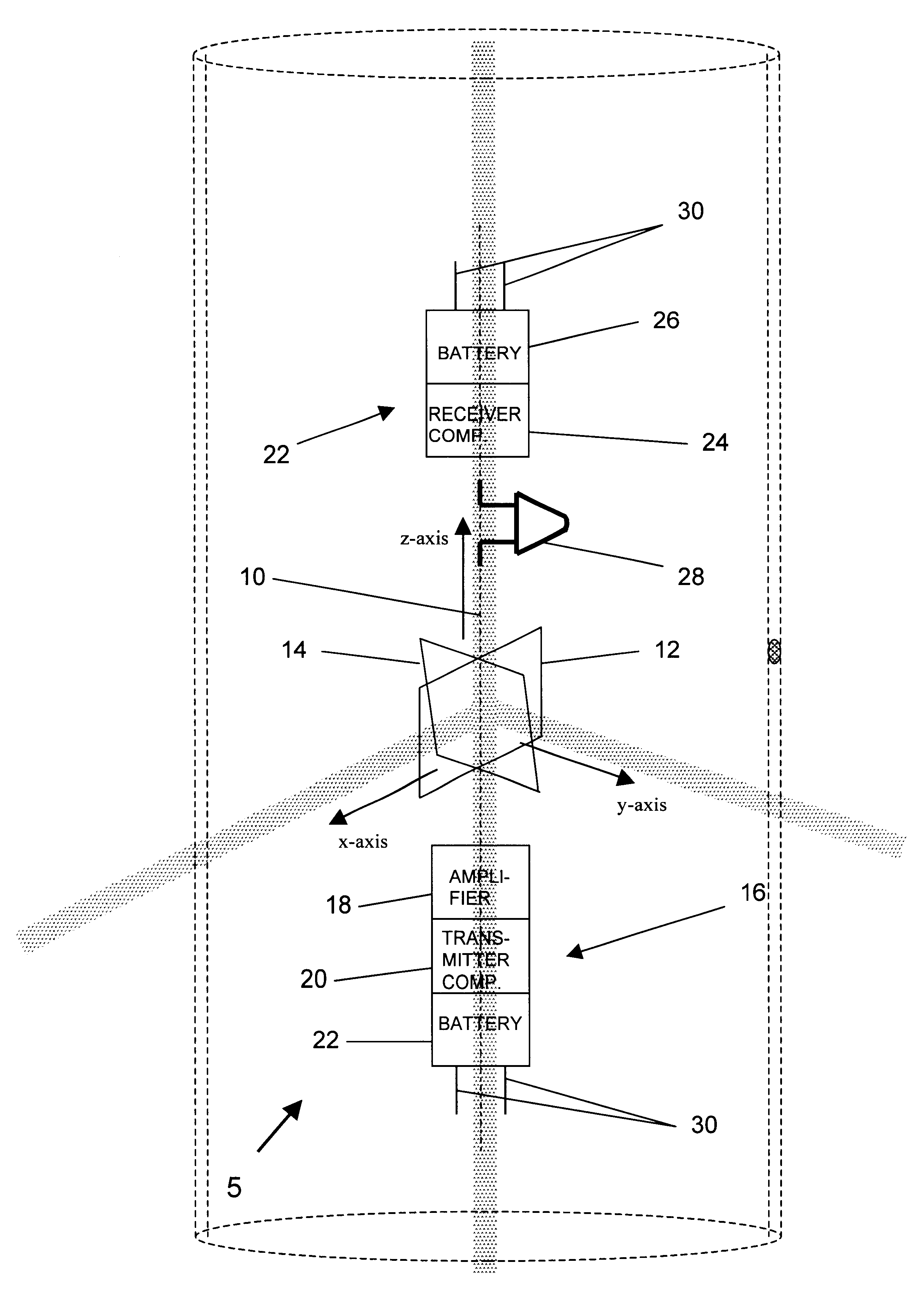
A method and tool using a continuous electromagnetic wave from a transverse magnetic-dipole source with a coaxial electric-dipole receiver is described for the detection of external sidewall cracks and other anomalies in boiler tubes and other enclosures. The invention utilizes the concept of radar backscatter rather than eddy-currents or ultrasound, which are sometimes used in prior art crack-detection methods. A numerical study of the distribution of the fields shows that the direct transmission from the source to the receiver is reduced from that in free space. Further, if the diameter of the receiver dipole is made sufficiently small, it should be possible to detect cracks with a scattering loss of up to -40 dB in thin-walled boiler tubes.

Description

1. Field of the InventionThis invention pertains generally to detecting cracks and other anomalies in tubes such as steam tubes used in boiler applications. A method and apparatus are disclosed in which, in the preferred embodiment, a transverse magnetic-dipole source positioned inside a tube generates a continuous electromagnetic wave and electric field parallel to the axis of the tube. The wave reflects off the external wall of the tube and returns to a coaxial electric-dipole receiver. The transmitting and receiving antennas are designed and positioned to minimize crosstalk and at the same time distinguish cracks and other anomalies in the tube based on the return signal.2. Description of the Related ArtHistorically, and even to the present day, the major cause of boiler outages is the degradation of the steam tubes by which heat is extracted from the boiler. Although there is deposition and corrosion upon the internal surfaces of the tubes, the principal cause of failure is by t...

Claims


Application Information

Patent Timeline
IPC IPC(8): G01N22/02G01N22/00
CPCG01N22/02
Inventor CAFFEY, THURLOW W. H.
Owner NAT TECH & ENG SOLUTIONS OF SANDIA LLC
Learn More