Binary code converters and comparators

a converter and binary code technology, applied in the field of binary code converters and comparators, can solve the problems of system ill-suited for safety critical systems such as flight control systems, system misinterpretation of one input, and slow technique,

Inactive Publication Date: 2001-07-17
BAE SYSTEMS PLC
View PDF8 Cites 18 Cited by
  • Summary
  • Abstract
  • Description
  • Claims
  • Application Information

AI Technical Summary

Problems solved by technology

However, this technique is slow and prone to both conductive and emissive radio frequency interference (RFI) as it relies principally on clocks, counters and microprocessors.
Both the speed of operation and susceptibility to disruption or corruption by other noise makes such a system ill-suited for safety critical systems such as flight control systems.
By way of illustration, a flight control system may need to make rapid de

Method used


Image

  • Binary code converters and comparators
  • Binary code converters and comparators
  • Binary code converters and comparators

Examples


Embodiment Construction

Thermometer Code Converter

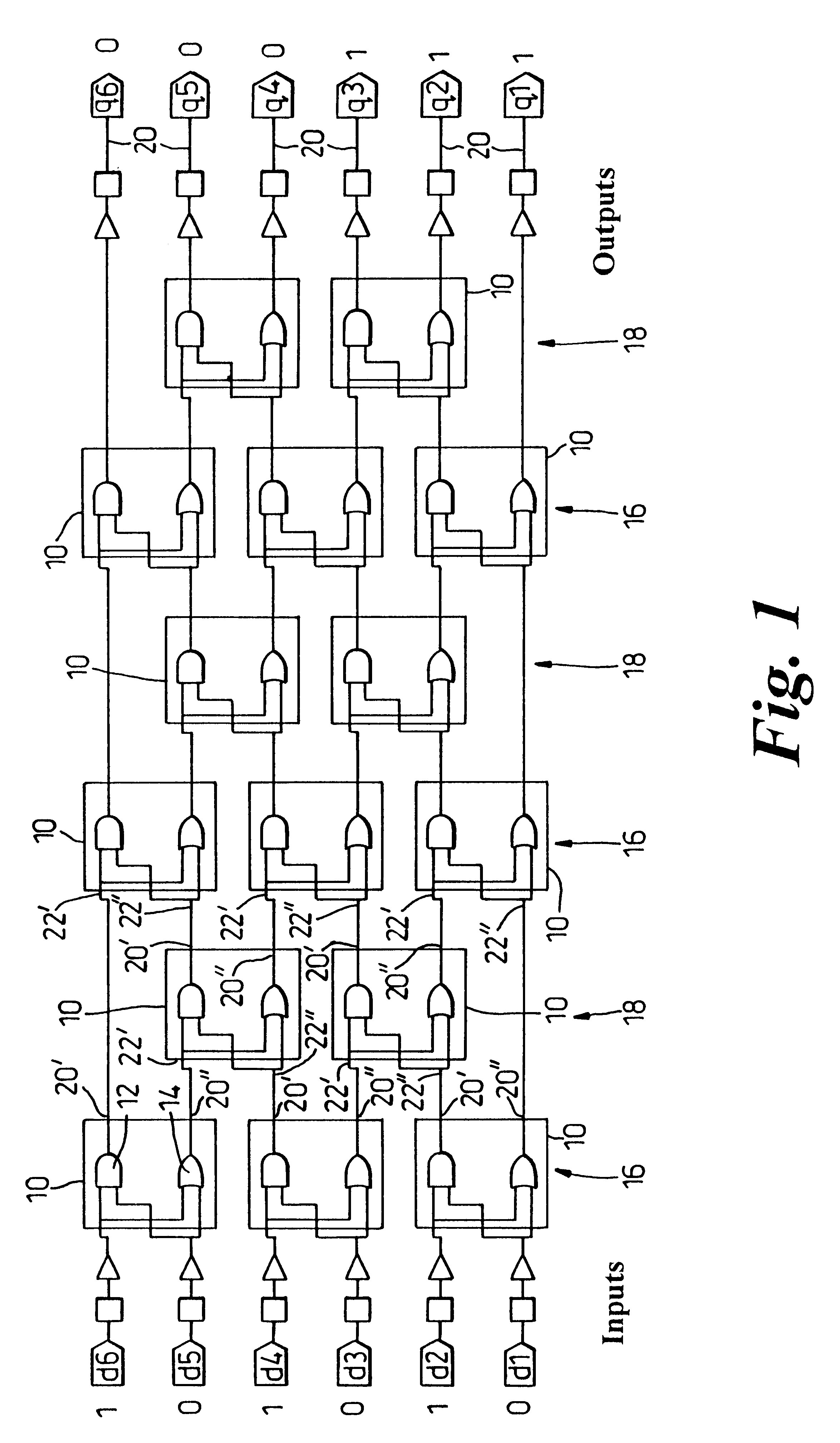
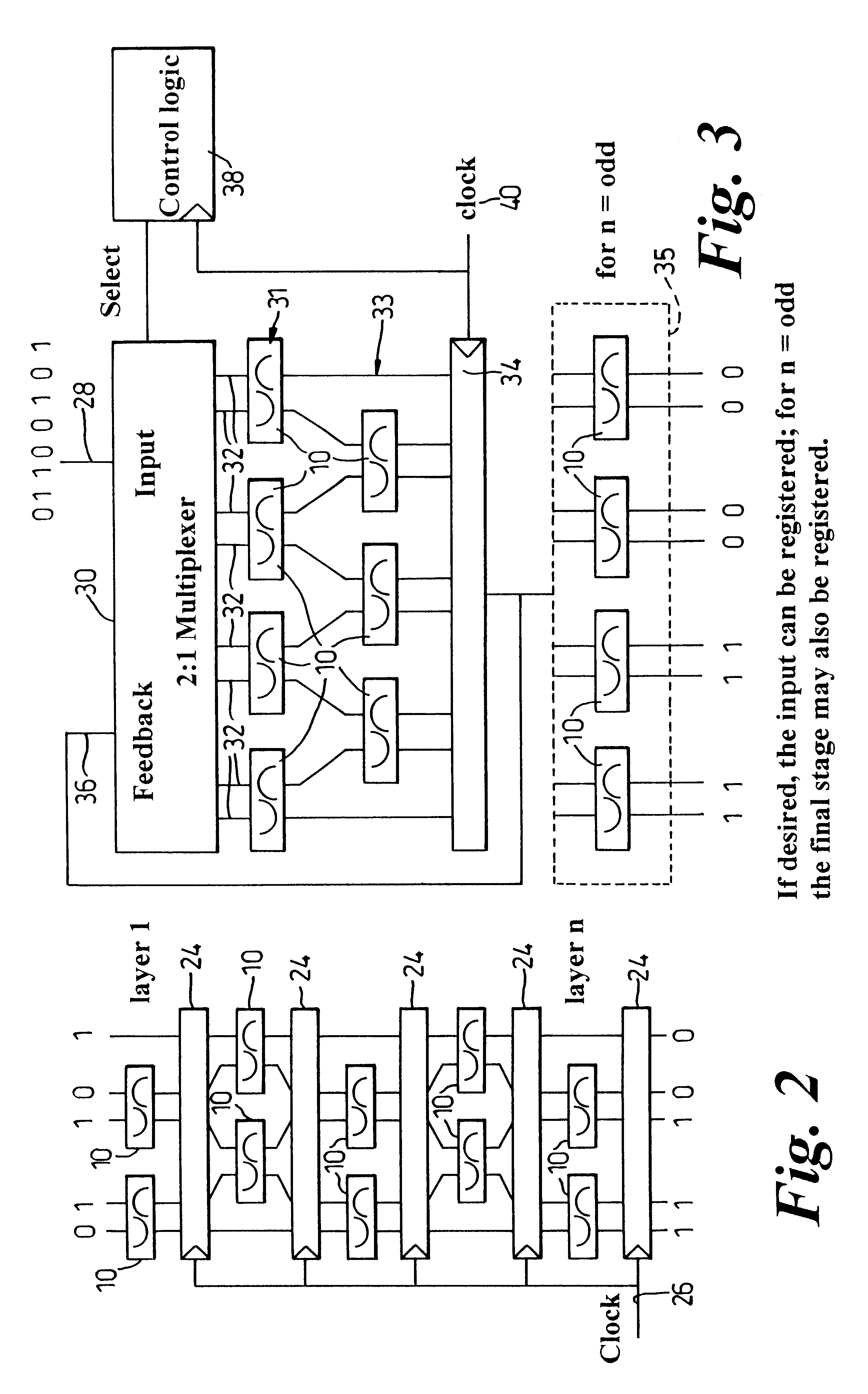
Referring now to FIGS. 1 to 3 of the drawings, there is shown an embodiment of thermometer code converter for converting a binary vector into thermometer code in various implementations. Each implementation makes use of a parallel array of bit manipulation cells 10 each having the same function. Each bit manipulation cell 10 has two inputs and two outputs and provides the following mappings:

Inputs (00) (01) (10) (11) are mapped to:

Output (00) (10) (10) (11)

In this mapping, if the leftmost bit is called B and the rightmost bit is called A, the logical mapping is:

B maps to A OR B and A maps to A AND B, or stated alternatively Yb=a & b, and Ya=a # b, where # is the OR function and & is the AND function, and Ya and Yb are the outputs.

Accordingly, it will be noted that each bit manipulation cell in this example comprises and AND gate 12 and an OR gate 14. The two input, two output bit manipulation cells 10 are arranged in alternate odd and even layers 16 and 18 ...


PUM


Abstract

A thermometer code converter for converting weightless binary tuples of 2 or higher dimensional arrays into a thermometer or aggregate code comprises a series of layers (16, 18) each made up of bit manipulation cells (10) which collectively cause set bits to be shifted towards a required bit position. The bit manipulation cells are made up of logic elements (12, 14) and the entire converter may be asynchronous. Also disclosed is a sum and threshold device which employs a thermometer code converter and a bit selector device.

Description

1. Field of the InventionThis invention relates to apparatus and methods for converting a weightless tuple or vector into thermometer code and also to apparatus and methods for determining the Hamming value comparator relationship of two thermometer codes or weightless vectors. The invention also extends to arrangements for converting 2-dimensional arrays of data into aggregate code in which set bits are aggregated or clustered around a focal bit position, in a manner analogous to that of converting 1-dimensional tuples or vectors, and such aggregate code is also referred to herein generally as thermometer code.2. Discussion of Prior ArtThe apparatus and methods described herein may usefully incorporate, utilise, be used with or be incorporated into any of the apparatus or methods described in our co-pending U.K. Patent Application No. 9726752.0 or our co-pending International Patent Applications Nos. PCT / GB98 / . . . , PCT / GB98 / . . . , PCT / GB98 / . . . , or PCT / GB98 / . . . (our Referenc...

Claims


Application Information

Patent Timeline
IPC IPC(8): G06F7/02G06K9/64G06N3/00G06N3/063G06T5/20H03M7/14H03M7/16G06N3/04G06N3/06
CPCG06F7/026G06K9/6202H03M7/165G06T5/20H03M7/16G06N3/063
Inventor KING, DOUGLAS B.S.
Owner BAE SYSTEMS PLC
Why Eureka
Try Eureka