
Conveyor belt

Inactive Publication Date: 2001-07-17
YOKOHAMA RUBBER CO LTD
View PDF24 Cites 15 Cited by
  • Summary
  • Abstract
  • Description
  • Claims
  • Application Information

AI Technical Summary

Benefits of technology

However, a certain specific fiber such as the high elongation polyester and the high elongation nylon used in the present invention which have not been used ordinarily in the conventional

Problems solved by technology

However, the conveyor belt of this kind is likely to be damaged due to abnormal deformation that occurs when foreign matters such as a cake adhering to pullies and falling transported materials are caught between the pullies and the conveyor belt.
Even tho

Method used


Image

  • Conveyor belt
  • Conveyor belt
  • Conveyor belt

Examples


Example

Incidentally, the synthetic fiber woven fabric of Example 6 was produced by using the warps obtained by arranging alternately the yarns of the ordinary polyester and the yarns of ordinary nylon, the synthetic fiber woven fabric of Example 7 was produced by using the warps obtained by mix-twisting the ordinary polyester fiber and the ordinary nylon fiber, and the synthetic fiber woven fabrics of other Examples and Comparative Examples used the yarns obtained by twisting the fibers of the materials tabulated in Table 1 for the warps.

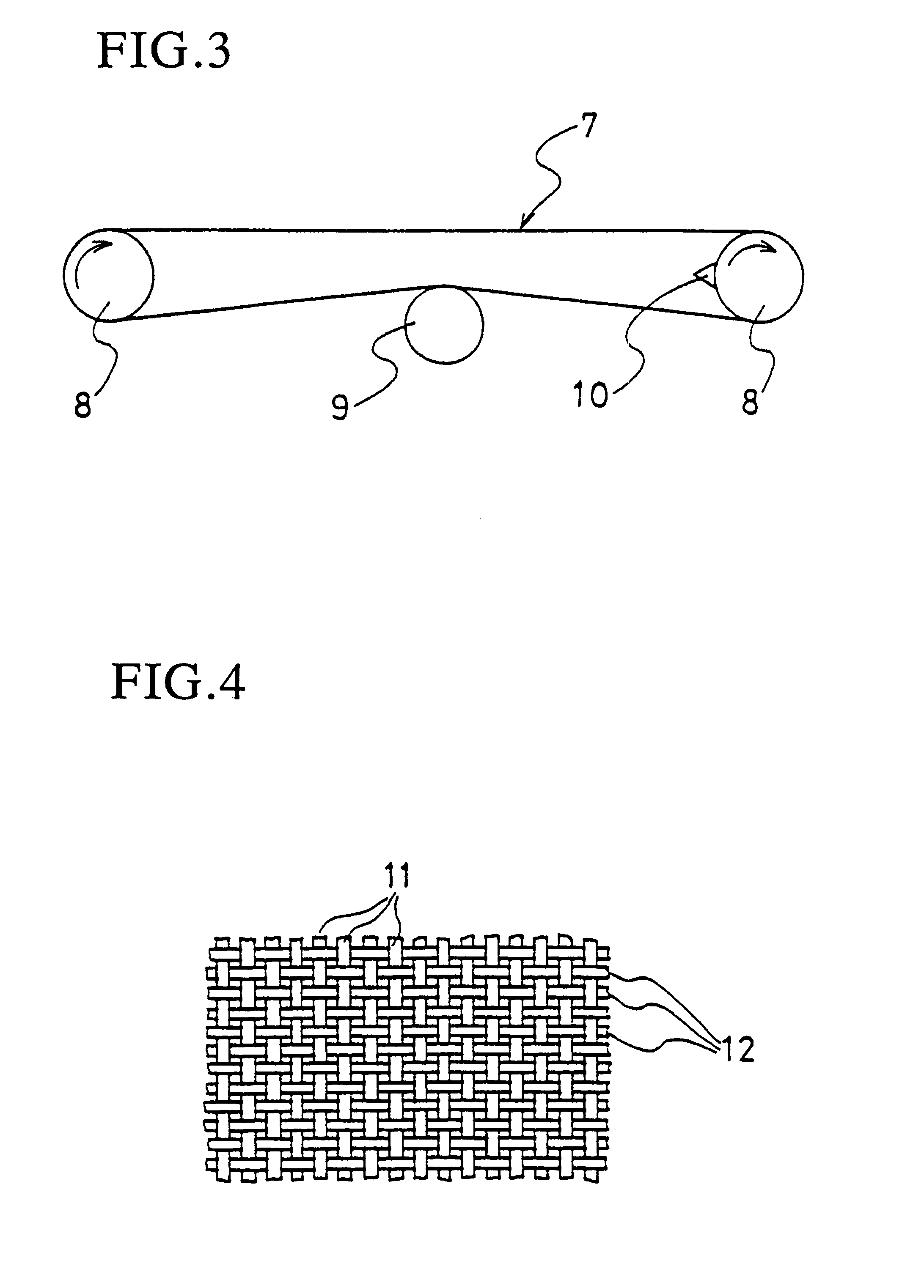
The fabric structure of the synthetic fiber woven fabric was the so-called "unicorn" fabric shown in FIG. 6 for all of the Examples and Comparative Examples.

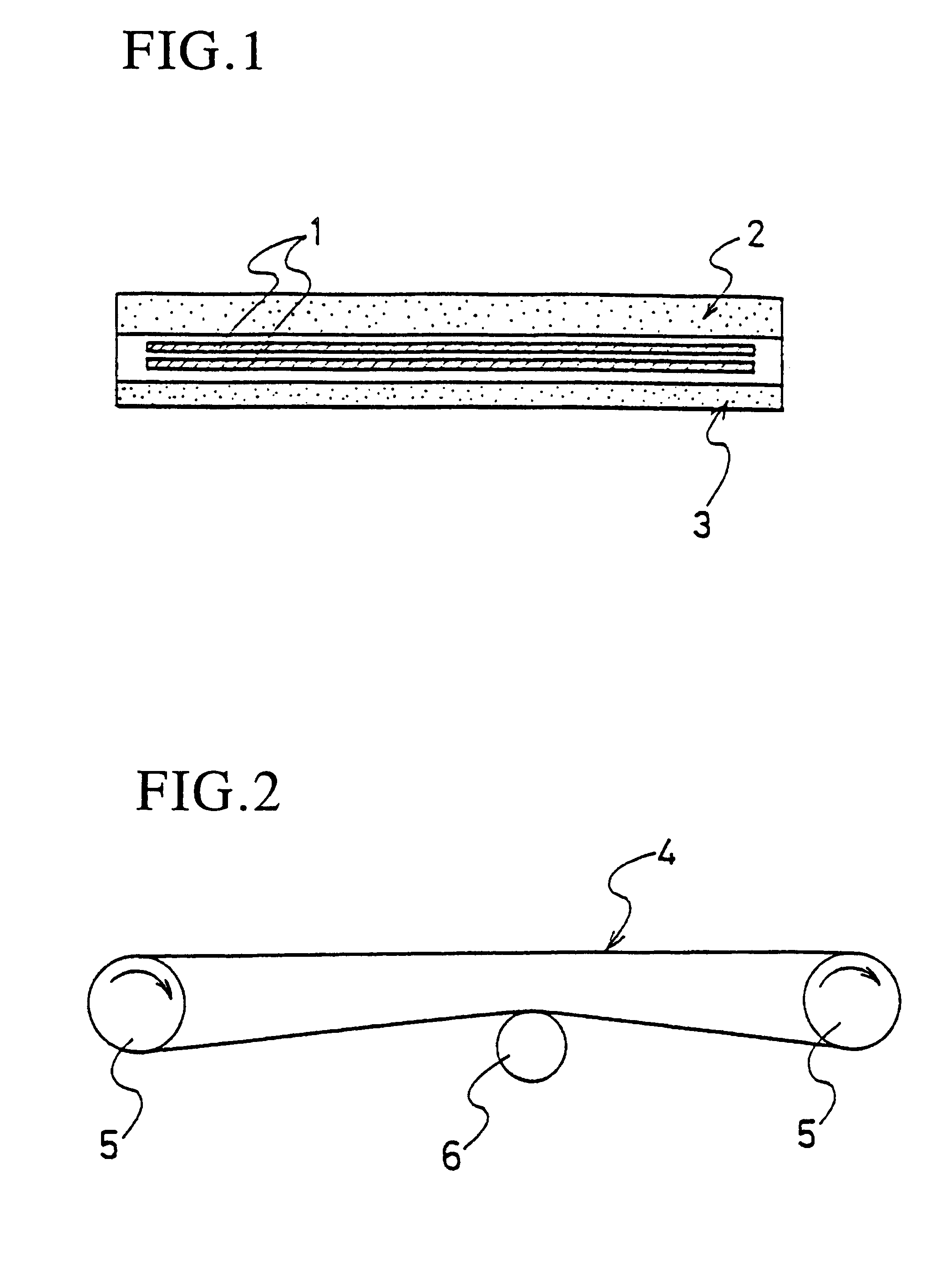
Next, the bending running test was carried out by a bending running tester shown in FIG. 2. Each belt testpiece 4 was passed around a pair of running pullies 5 and 5 and was pressed by a bend pulley 6. The elongation at a load 10% of the belt guarantee strength and the elongation at break were measured...


PUM

PropertyMeasurementUnit
Angleaaaaaaaaaa
Lengthaaaaaaaaaa
Elongationaaaaaaaaaa

Abstract

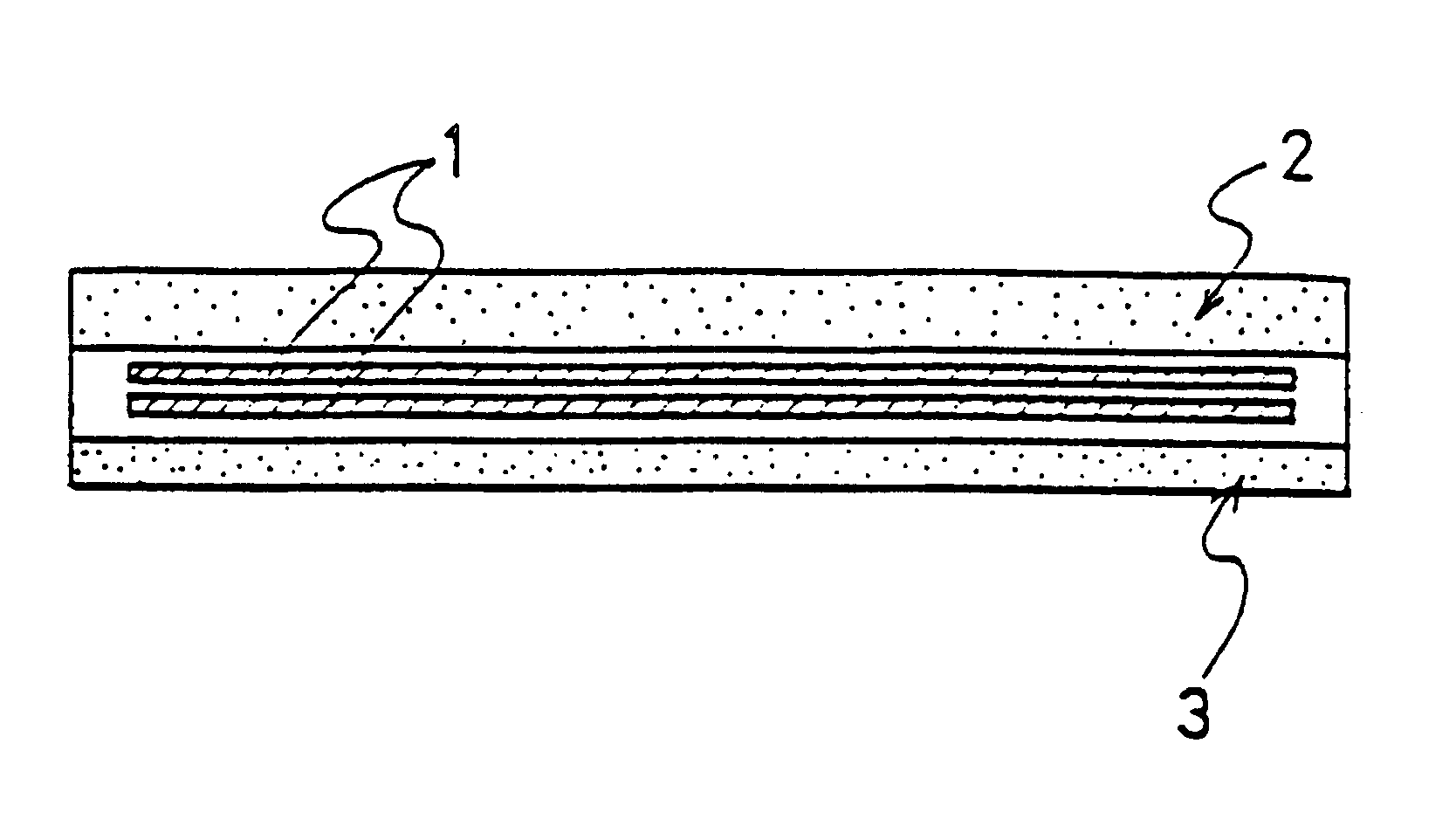
A conveyor belt having a reinforcing layer of a synthetic fiber woven fabric embedded between an upper surface cover and a lower surface cover, wherein an elongation at break of the synthetic fiber woven fabric in a belt longitudinal direction is at least 25% and an elongation at a load 10% of a guarantee strength is not greater than 1.5%.

Description

This invention relates to a conveyor belt reinforced by a synthetic fiber woven fabric. More particularly, the present invention relates to a conveyor belt which exhibits a small elongation in the course of its use for an extended period and is hardly damaged by foreign matters caught between pullies and a conveyor belt.Woven fabrics of a nylon fiber or a polyester fiber have been used in the past as a reinforcing layer of conveyor belts.However, the conveyor belt of this kind is likely to be damaged due to abnormal deformation that occurs when foreign matters such as a cake adhering to pullies and falling transported materials are caught between the pullies and the conveyor belt. Even though abnormal deformation is not of the level which directly results in the damage of the belt, repetition of such abnormal deformation lowers the strength of the belt due to its fatigue and consequently, the conveyor belt cannot withstand an extended use.In the conveyor belt of this kind, elongatio...

Claims


Application Information

Patent Timeline
IPC IPC(8): B32B27/02B32B27/12B65G15/32B65G15/34D03D15/00
CPCB32B27/02B32B27/12B65G15/34D03D1/0094D03D15/0027D03D15/00B65G2201/06Y10S198/957D10B2331/02D10B2331/04D03D15/47D03D15/283B32B25/12B32B25/14B32B25/10B32B2262/0276B32B2262/0261B32B2433/02B32B2262/14B32B5/024
Inventor SASHIDE, KAZUOTANAKA, SHIGEYASUSHINOHARA, OSAMUSHIMOTASHIRO, YUJISUZUKI, TERUOTODA, OSAMUYAMAMOTO, ICHIROKATSUMATA, SHINICHIMORI, KOJIROFUKUCHI, YOSHIMITSU
Owner YOKOHAMA RUBBER CO LTD
Learn More