Eureka AIR delivers breakthrough ideas for toughest innovation challenges, trusted by R&D personnel around the world.

Variable-air-volume diffuser actuator assembly and method

a technology of actuator and variable air volume, which is applied in the direction of ventilation system, heating type, instruments, etc., can solve the problems of diffuser assembly, small amount of sensor/actuator wax that will diffuse through pores, and requires considerable time not to work

Inactive Publication Date: 2001-06-26
ACUTHERM
View PDF15 Cites 61 Cited by
  • Summary
  • Abstract
  • Description
  • Claims
  • Application Information

AI Technical Summary

Benefits of technology

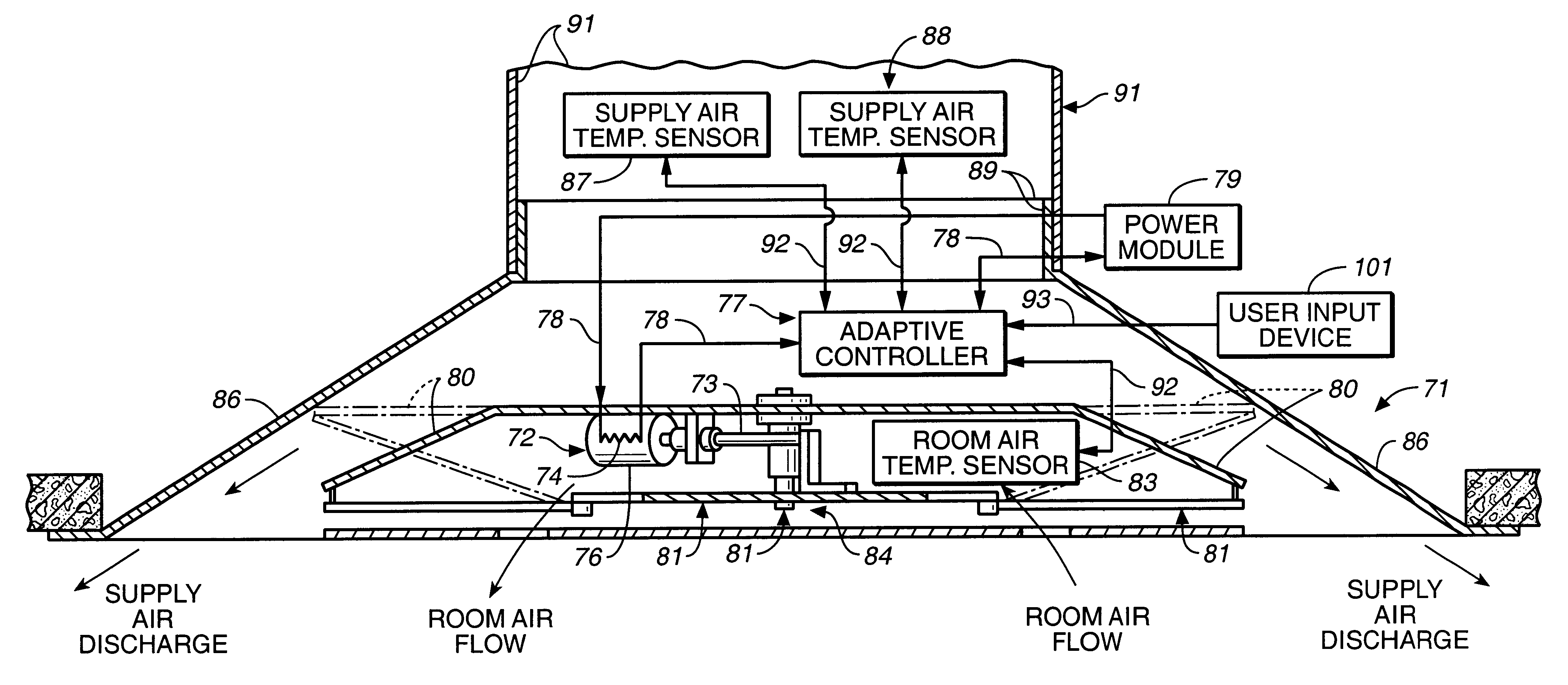
In the most preferred embodiment, the actuator assembly is used to power a variable-air-volume diffuser with the movable element positioned to effect displacement of a damper which controls the discharge of supply air from the diffuser assembly into a space or room. The sensor can be provided by a room air temperature sensor, but most preferably it also includes a supply air temperature sensor and a supply air flow rate sensing assembly. The adaptive control circuit controls operation of the actuator and therefore movement of the damper in response to input from the various sensors so as to adaptively vary the volume of supply air discharged from the diffuser in response to sensed room air temperature.

Problems solved by technology

All of these prior art VAV actuators, however, have deficiencies which, if eliminated, would enhance their performance.
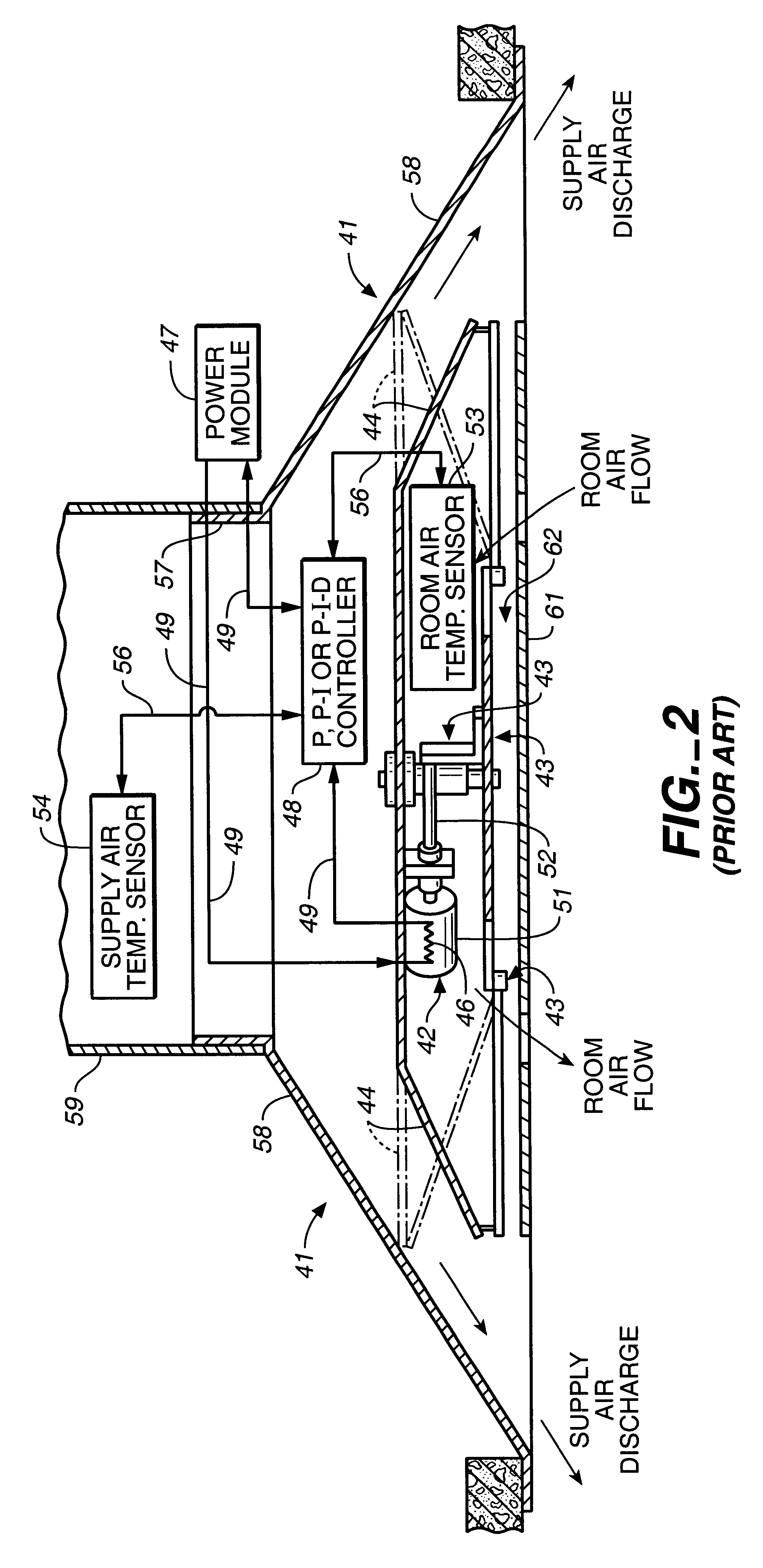
Another source of hysteresis in thermally-powered, VAV, diffuser assemblies is the mechanical linkage between the thermal actuator and the movable damper.
Small amounts of sensor / actuator waxes will diffuse through pores in rubber seals over long time periods.
Thus, over a weekend, the mass of a room may cool or heat to the ambient temperature, requiring considerable time not only to heat or cool the air in the room, but also to heat or cool the mass of the walls defining the room and the furnishings in the room.
Such compensation techniques can solve upstream problems, but they do not solve the downstream problem of unequal pressure drops between the VAV box and the individual damperless diffusers.
The air volume discharged at each downstream, damperless diffuser, therefore, will be unbalanced (unequal) by the differences in pressure drop from the VAV box to the various individual diffusers.
This is normally "corrected" through the use of pressure-balancing dampers in the supply air duct proximate each diffuser, but such balancing dampers add to the cost and only "balance" the system for one set of conditions, i.e., when the flow rates change, the system becomes unbalanced again.
Many of these same problems, or analogous problems also exist in VAV diffuser systems which are driven by electric motors.
Moreover, gear-based or lever-based damper opening mechanisms coupled to the electrical motor can exhibit hysteresis effects on motion reversals, which are analogous to hysteresis losses in linkages in thermal diffusers.
Since the speed of an electric motor response is constant, but it can be either too fast or too slow.
Thus, electric motor powered systems also can have problems with constant "hunting" about the set point temperature due to over-responsive or under-responsive performance.
Even this refinement, for example, a tunable PID control system, does not solve the problem of thermal demand variations.
If the room conditions fall outside the control envelope, however, PID systems often lose their ability to drive the room temperature back inside the control envelope within a reasonable time period, if at all.
The problem with PI VAV systems can be that the system constantly hunts for the set point as the PI algorithm drives it too fast past the set point in both directions or moves too sluggishly toward the set point.
Generally, the cost and complexity of such controllers has made their use with individual VAV diffusers prohibitive.
Moreover, such adaptive systems have not been integrated to control thermally-powered sensor / actuators.

Method used


Image

  • Variable-air-volume diffuser actuator assembly and method
  • Variable-air-volume diffuser actuator assembly and method
  • Variable-air-volume diffuser actuator assembly and method

Examples


Embodiment Construction

The most preferred embodiment of the present invention is a variable-air-volume diffuser which is adaptively controlled to respond to sensed room air temperature so as to intelligently and autonomously control the volume of supply air discharged into a room or space. The present invention, however, has applications beyond HVAC systems. Thus, an actuator which is adaptively controlled using the teaching of the present invention can be applied, for example, to the operation of valves for the control of the flow of liquids. Similarly, the present invention is most preferably directed to the control of wax-based thermal actuators, but it also may be used to adaptively control the operation of other thermal actuators, such bimetallic or memory metal thermal actuators, and to control the operation of non-thermal actuators such as electric motors, piezo-electric actuators, pneumatic actuators and hydraulic actuators, among others.

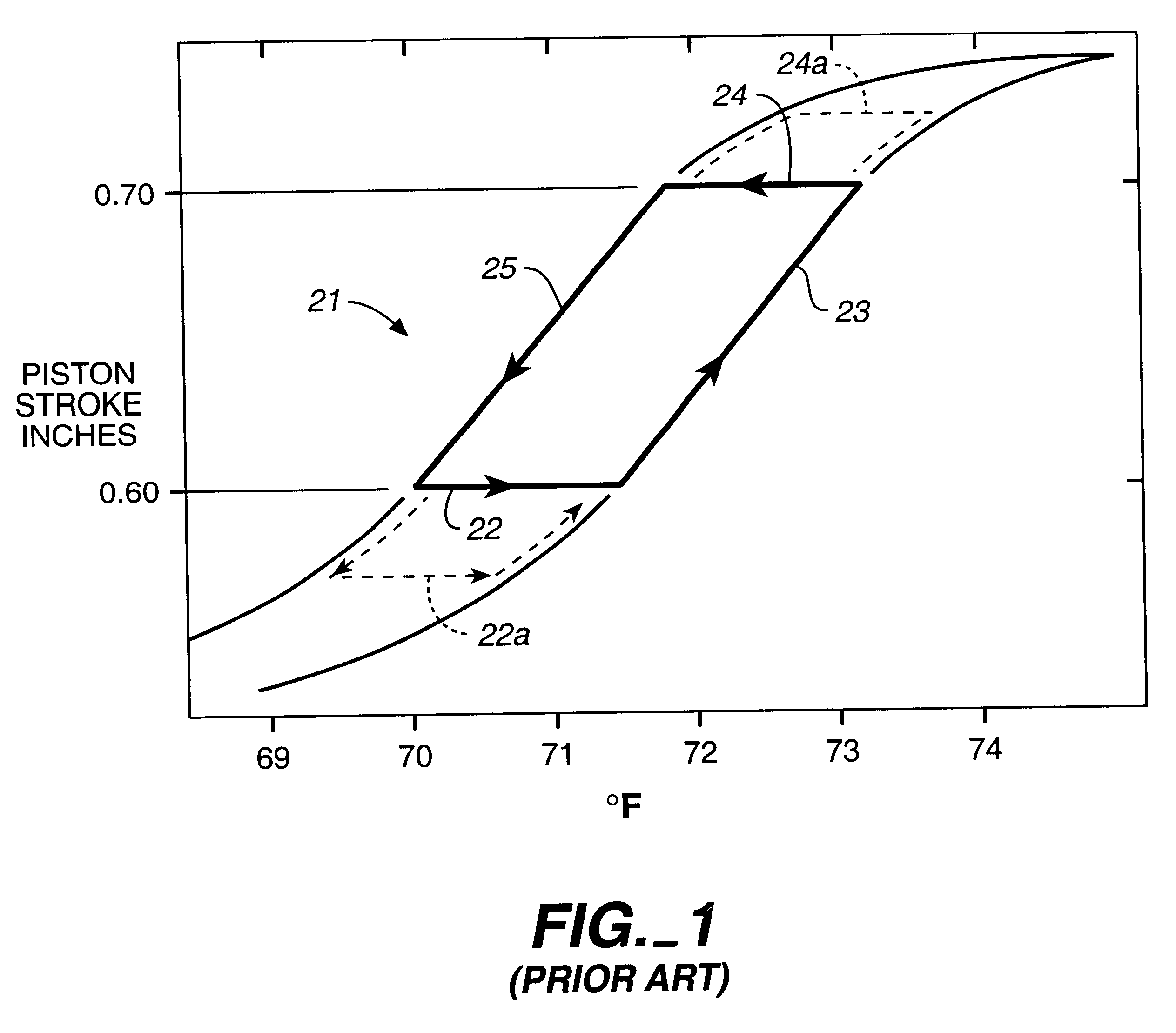
As seen from FIG. 1, thermal actuators conventionally have h...


PUM


Abstract

An adaptive control device (77) and method (102-108) for control of the operation of an actuator (72), and particularly thermally-powered actuator (72) of the type used in a variable-air-volume diffuser (71). The preferred adaptive control device is an expert system circuit which controls a heater (74) provided on a thermally-powered actuator (72) to implement an adaptive process (102-108) in which a sensed variable, such as room air temperature, is driven toward a target temperature control range (±0.25° F.). Most preferably, the process steps (106) include driving the room air temperature toward a gross (broader) temperature control range (±1.0° F.) by moving a diffuser damper assembly (80) to a substantially fully open or substantially fully closed position. Thereafter, and while inside the gross temperature control range, the process steps (107, 108) include adjustments to the position of the damper assembly (80) are made only when a sensed parameter, preferably the supply air flow rate, is in a stable condition. Most preferably, the damper (80) is temporarily "kicked" farther open or farther closed than necessary, to minimize hysteresis effects, and then adjusted to a posiiton which tends to drive the room air temperature into the narrower, targeted temperature control range.

Description

The present invention relates, in general, to heating, ventilating and air conditioning (HVAC) system and actuators therefor, and more particularly, relates to thermally-powered actuators for variable-air-volume diffusers.In variable-air-volume (VAV) diffusers, room air temperature is controlled by varying the volume of supply air which is discharged into a room. The supply air will be heated when the VAV system is in a heating mode and it will be cooled when the system is in a cooling mode. The supply air is usually provided at substantially a constant temperature for each mode. A variable-air-volume diffuser, or an upstream VAV box, is used to regulate the volume of heated or cooled supply air in order to achieve and maintain the desired room air temperature. A central building controller is used to determine whether hot supply air or cool supply air flows from the HVAC air source to the VAV diffusers or box. It is possible, of course, for only cool air or only hot air to be suppl...

Claims


Application Information

Patent Timeline
Patent Type & Authority Patents(United States)
IPC IPC(8): F24F11/04F24F11/00F24F11/053G05D23/19G05D7/06F24F11/76
CPCF24F11/006F24F11/053G05D7/0635G05D23/1919F24F11/0012F24F2011/0013F24F2011/0038F24F11/30F24F2110/10F24F2110/12F24F2110/30F24F11/62F24F11/76F24F11/64
Inventor KLINE, JAMES R.HUNKA, ROBERT S.COSTICK, MATTHEW L.
Owner ACUTHERM
Why Eureka
Eureka Blog
Learn More