
Print head cartridge and method of making a print head cartridge by one-shot injection molding

a printing head and injection molding technology, applied in printing and other directions, can solve the problems of ink reservoir leakage, frame 10 almost twice as expensive to manufacture as a similar frame, and print head cartridges made by the two-shot molding process

Inactive Publication Date: 2001-06-05
FUNAI ELECTRIC CO LTD
View PDF7 Cites 32 Cited by
  • Summary
  • Abstract
  • Description
  • Claims
  • Application Information

AI Technical Summary

Problems solved by technology

The prior art print head cartridges shown in FIGS. 5-8 has a disadvantage in that the frame requires two separate and distinct molding steps thus making the frame 10 almost twice as expensive to manufacture as a similar frame formed in a single molding step.
As discussed in EP published application 0 561 051, print head cartridges made by the two-shot molding process have a further disadvantage in that the ink reservoir may leak where the inner frame 18 is molded around the standpipe 24.

Method used


Image

  • Print head cartridge and method of making a print head cartridge by one-shot injection molding
  • Print head cartridge and method of making a print head cartridge by one-shot injection molding
  • Print head cartridge and method of making a print head cartridge by one-shot injection molding

Examples


Embodiment Construction

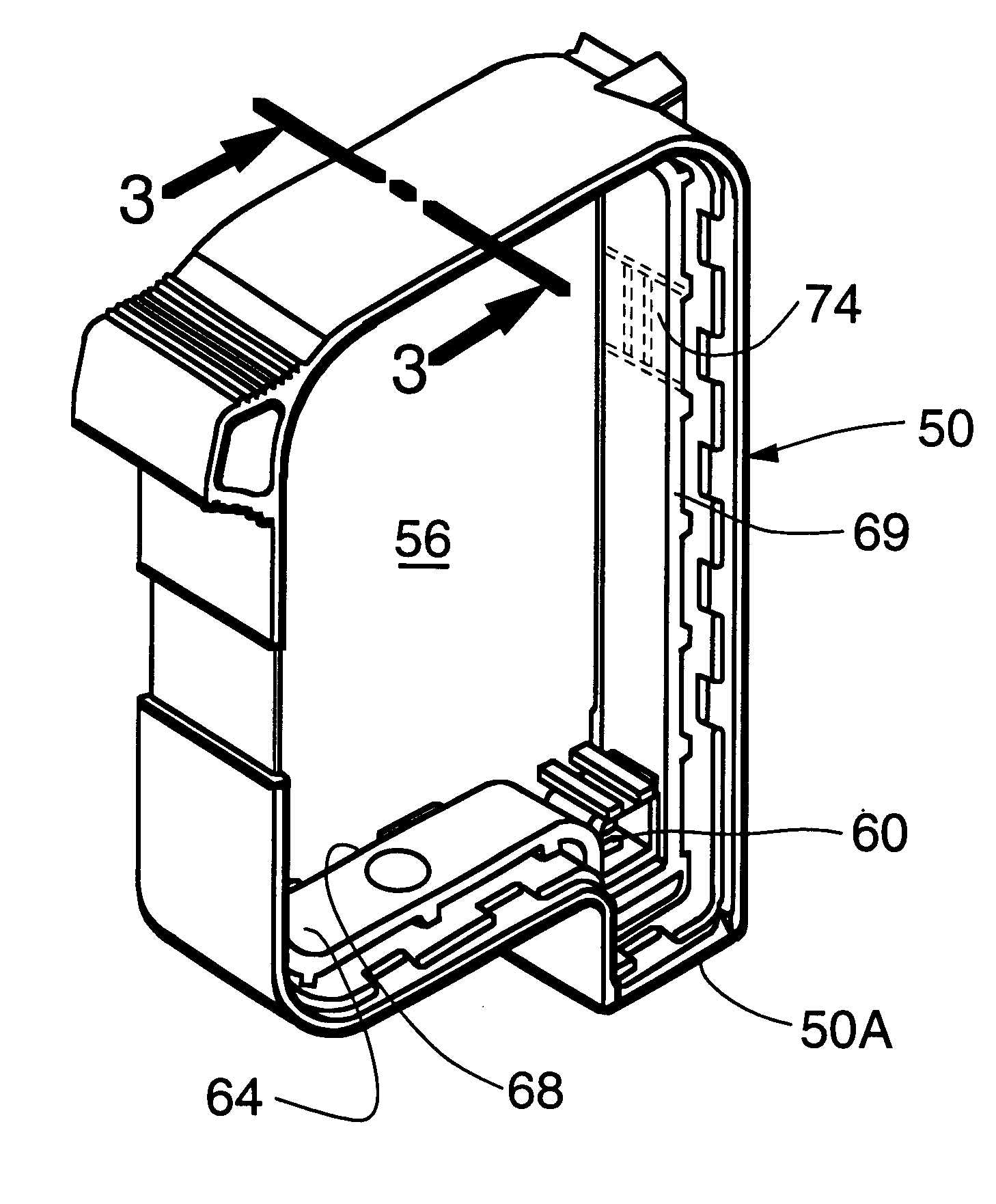
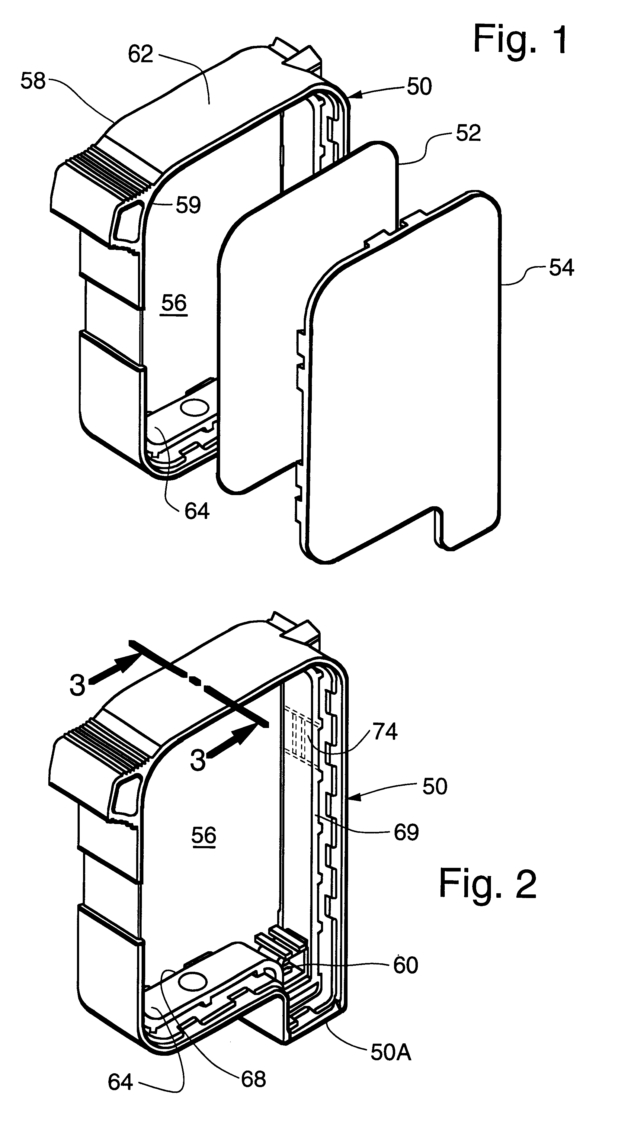
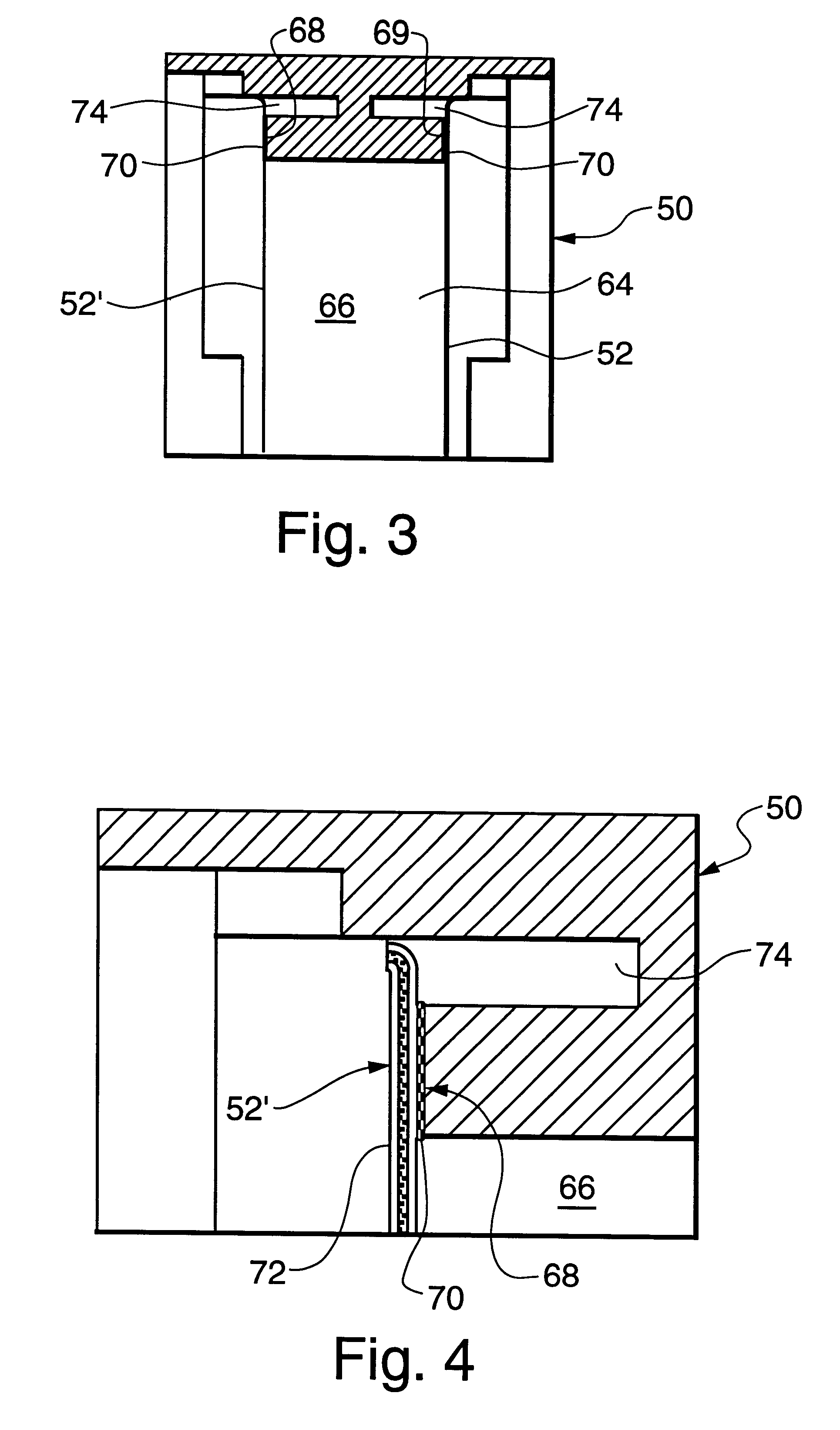
FIGS. 1-4 illustrate a print head cartridge constructed according to the present invention. The cartridge includes a rigid frame 50, two flexible ink-impervious thin films 52,52' (FIG. 3) and two side covers 54, only one of the covers being shown in FIG. 1. The term `thin film` as used herein means a thin, flexible sheet of material which may or may not be transparent.

The rigid frame 50 is a monolithic structure formed by plastic injection molding in a single molding step so as to have the configuration shown in FIG. 2. The term `monolithic structure` as used herein means a structure that is massively solid and uniform. That is, it consists of a single mass or piece and is substantially uniform in content, like an object obtained by injection molding. Rigid frame 50 is molded with a large opening 56 extending through it from a first side 58 to a second side 59. The exterior surface 62 of the rigid frame 50 comprises the peripheral outer surface of the cartridge. The interior surface...


PUM


Abstract

A print head having an ink reservoir therein is made by forming, in a one-shot plastic injection molding step, a rigid monolithic frame comprising high melt temperature material having an opening therein extending from a first side to a second side, and first and second bonding surfaces surrounding the opening and facing the first and second sides, respectively. First and second thin flexible films are adhesively secured to the first and second bonding surfaces, respectively. The adhesive material may be a hot melt adhesive or dry adhesive films pre-formed to the shape of the bonding surfaces. By securing the flexible films to the bonding surfaces adhesively, rather than by heat staking, it is not necessary to form the frame of different materials during two separate molding steps.

Description

1. Field of the InventionThe present invention relates to cartridges for ink jet print heads of the type wherein the ink reservoir is bounded by two thin films and a rigid frame. The invention provides novel cartridges made by a process wherein the frame is formed in a one-shot plastic injection molding step and the thin films are attached to the frame by adhesive bonding.2. Prior ArtHigh capacity color ink jet printers configured around independent single color pens are currently commercially available. Typical pens or cartridges of the type suitable for use in such printers are shown in U.S. Pat. Nos. 5,280,300 and 5,325,119 and EP published applications 0 561 051 and 0 583 153.As shown in FIG. 5 a typical prior art print head cartridge includes a frame 10 having a flexible ink-impervious thin membrane 12 and a side cover 14 disposed on one side. A second membrane and a second side cover (not shown) are disposed on the opposite side of frame 10. The frame 10 is formed by a two-sho...

Claims


Application Information

Patent Timeline
Patent Type & Authority Patents(United States)
IPC IPC(8): B41J2/175B41J2/16
CPCB41J2/17513B41J2/17553
Inventor BRANDON, FRED YOUNGCHRISTIANSEN, ROBERT ARNOLDDROEGE, CURTIS RAYSTEWARD, LAWRENCE RUSSELLWILLIAMS, GARY RAYMOND
Owner FUNAI ELECTRIC CO LTD
Learn More