Adjustable microwave field stop

Inactive Publication Date: 2001-06-05
EWES ENTERPRISES L L C
View PDF30 Cites 34 Cited by
  • Summary
  • Abstract
  • Description
  • Claims
  • Application Information

AI Technical Summary

Benefits of technology

The method and apparatus of the invention, using microwave energy which passes through the billet, is reflected back into the billet, is sensed, and the microwave energy tuned to reduce the reflected microwave energy to approximately zero, thus optimizes the use of energy to heating a billet of fibrous material and binder material to be pressed into dimensioned material, such as engineered wood products. If used in a preheating step before the billet enters a press, the microwave energy heats the billet to a temperature which is optimal for curing in the press and which decreases the amount of heat necessary to be applied to the billet while it is in the press. Since the microwave energy is applied by a number of microwave applicators normal to the longitudinal plane of the billet, a billet of any width can be accommodated. Since the energy is applied normal to the plane of the glue lines, the danger of arcing or tracking of the energy through the glue lines is reatly reduced. Since the energy is applied through a number of tuning systems which are being continually adjusted for optimal energy delivery as the billet travels through the microwave heating apparatus, this apparatus accounts for variations in density, moisture content of the material, moisture content of the binder, and other variables in the billet to deliver a uniform distribution of heat to the center of the billet.

Problems solved by technology

Since wood is a good insulator, transferring heat through wood by conductance has certain limitations.
This reflected and dissipated microwave power is wasted and is not used in the heating of the wood product.
However, a problem that has been encountered with the use of RF energy is that when RF is directed into a billet of veneer and glue layers in a direction parallel to the glue lines, and where the glue used is an alkaline solution of phenol formaldehyde resin, which is the most common of binding agents, the energy can cause arcing and tracking, especially along the layer of glue.
The thicker the layer of glue, or the higher the water content of the glue, the more that the arcing and tracking becomes a problem.
The reason for this undesirable effect is a relatively high conductivity of the resin which can lead to breakdown as the electric field from the microwave is integrated along a single axis.
Another problem encountered in making engineered wood products is that energy directed into the billet while it is under pressure can cause moisture within the layers of wood to flash or boil away rapidly.
When the pressure on the billet is released, if the pressure from expanding gasses is greater than the strength of the binding material holding the wood fibers together, the expanding gasses can cause a blowout.
Still another problem encountered in making engineered wood products which are heated by microwaves directed from the side of the billet toward the center of the billet while the billet is under pressure in a press is that the width of material through which the microwave energy can pass so that the center of the material is heated is limited.
Billets which are very much wider than 24 inches are difficult to heat from side applied microwave energy.
If these billets are not only wide in the lateral dimension, but also thick in the dimension normal to the longitudinal axis, they are also difficult to heat by conduction from the press platens because of their thickness.
Therefore, the thickness of billets is limited by the prior art techniques of heating through conduction from the press platens and side directed microwave energy in the press.
Another problem with the current technology of preparing engineered wood products is that the process is fairly sensitive to variations in moisture content.
This preparation of the wood fiber is expensive and time consuming.

Method used


Image

  • Adjustable microwave field stop
  • Adjustable microwave field stop
  • Adjustable microwave field stop

Examples


Embodiment Construction

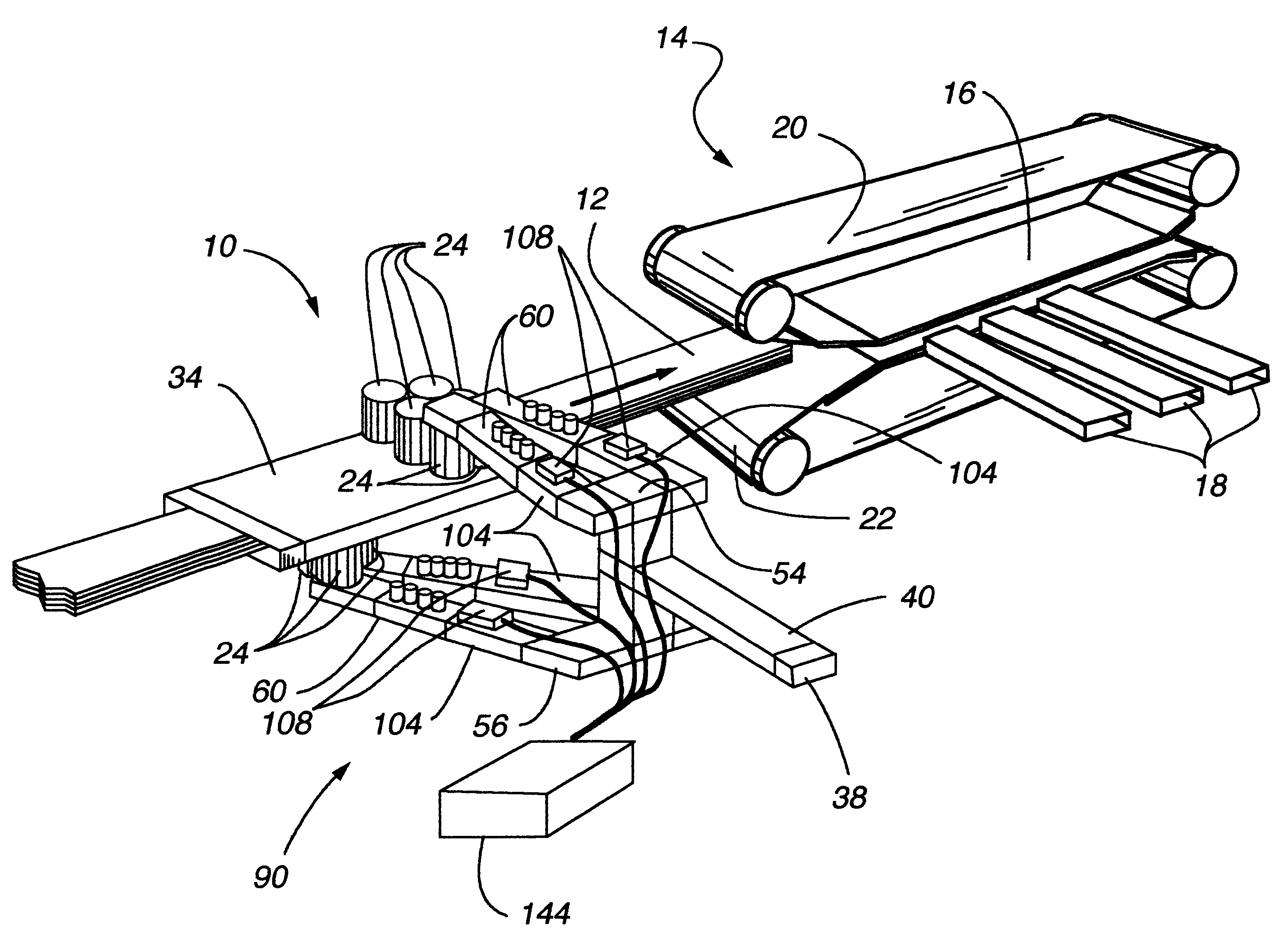
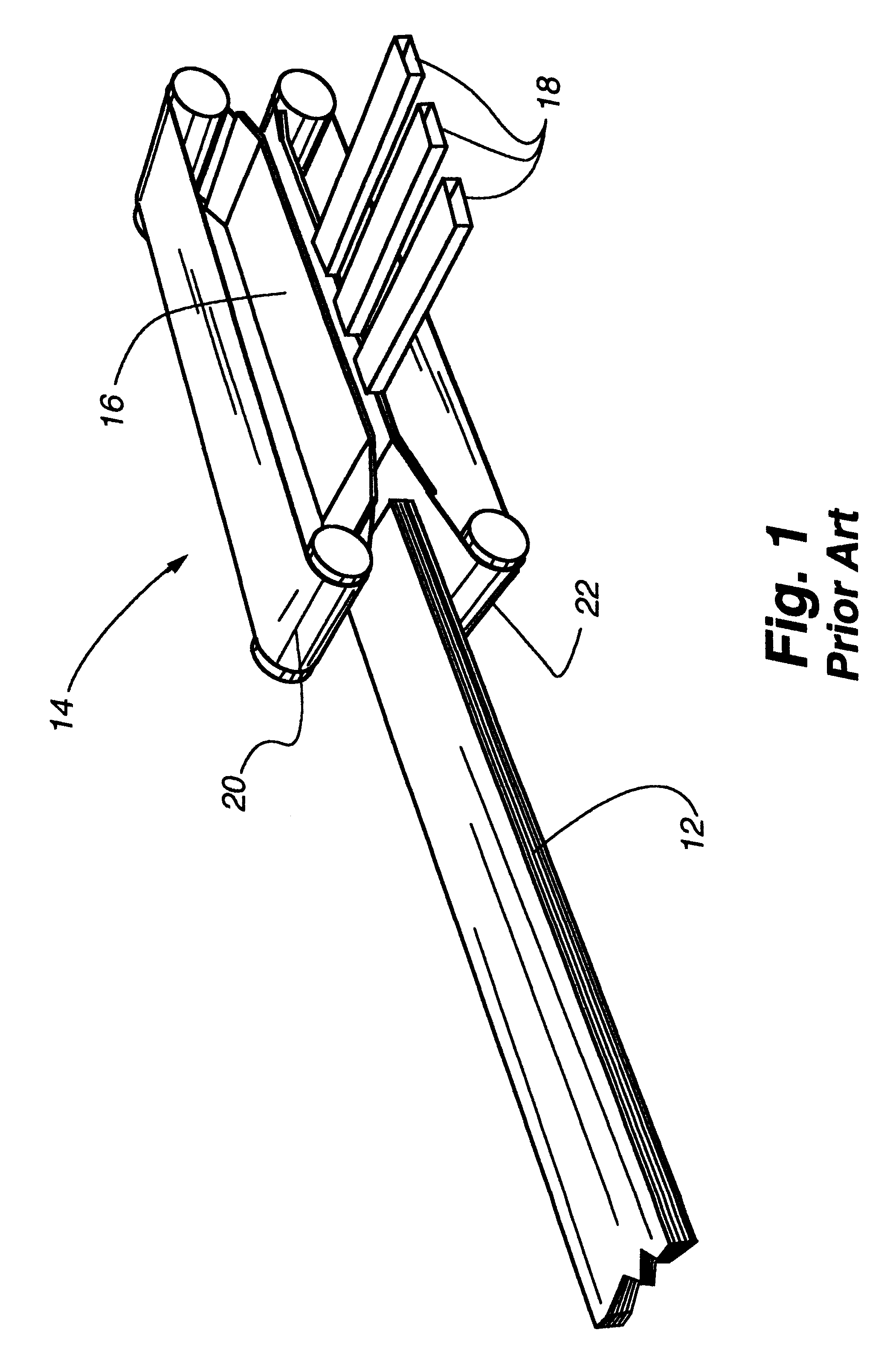
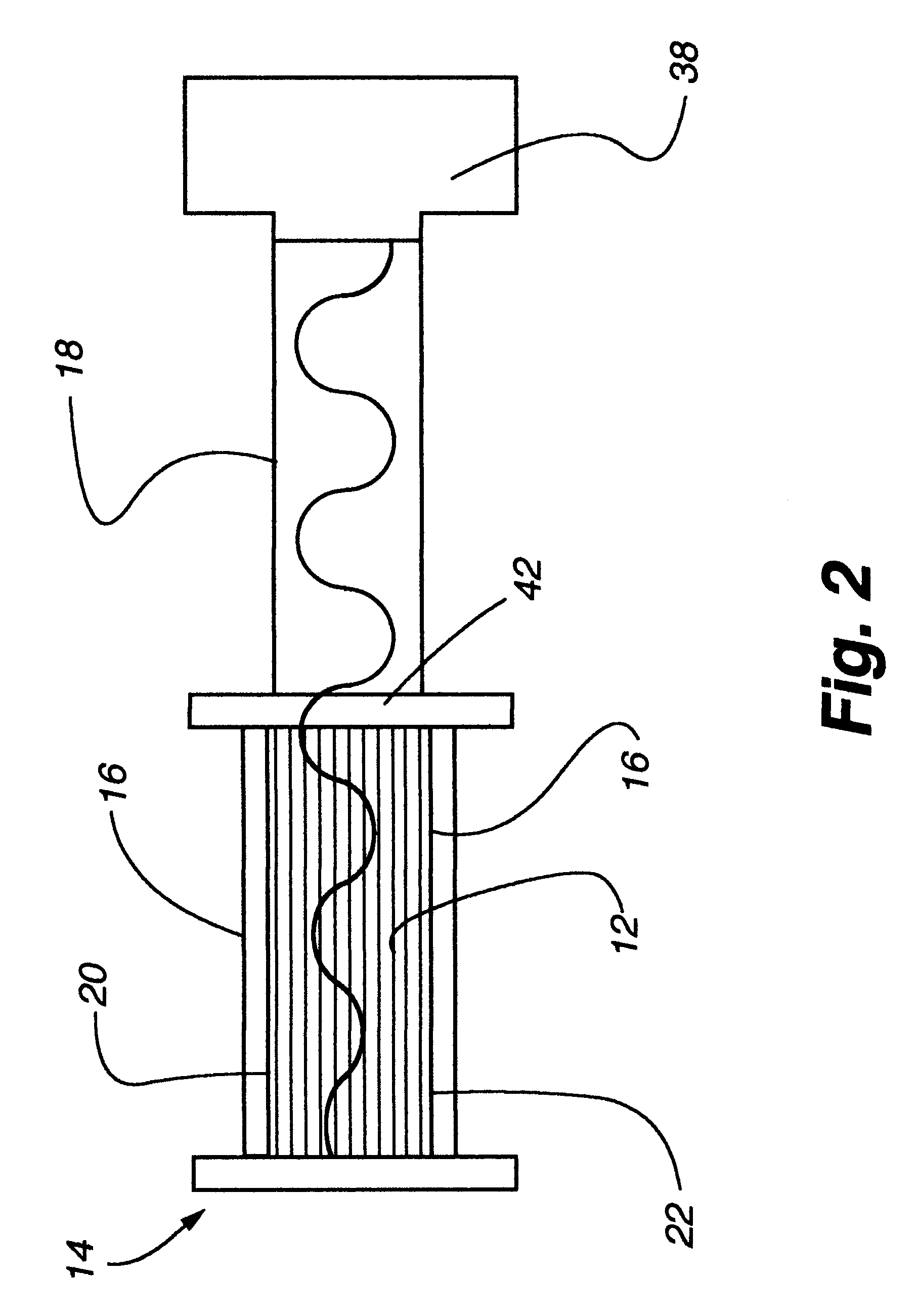
Referring to FIGS. 1 through 12, the invention is shown to advantage. FIG. 1 shows a simplified view of a prior art system for gluing veneer strands together to form engineered wood using the application of microwave energy while the work piece is in a press 14. Although the work piece 12, which hereinafter will be referred to as a billet, could be of any thickness, in-press heating with microwave energy is best suited for thicker billets, to utilize the characteristic of microwaves to penetrate and heat the center of a billet. In the prior art, the billet 12 is composed of layers of wood strands and glue (also known as binding material or adhesive). The billet enters a press 14 which consists of an upper continuous belt 20 and a lower continuous belt 22. The two belts are brought together in the press platen 16, which applies pressure to the billet. As shown in FIG. 2, while the billet 12 is in the platen 16 of the press 14, microwave energy from a source 38 is directed into rectan...


PUM


Abstract

An improved magnetic field stop. The field stop adjusts to allow different sizes of products to be passed through a microwave heating system. The field stop prevents undue radiation from escaping a heating chamber which is used in a microwave heating process for a variety of substrates.

Description

DESCRIPTION1. Technical FieldThis invention relates to an apparatus and a method for the manufacture of engineered wood products, and more particularly to the use of microwaves to accelerate the curing of resins used in engineered wood products.2. BackgroundEngineered wood products are made by combining wood fibers and a resin which hardens as it cures and binds the fibers together.Traditionally, wood fiber in the form of layers of veneer or pieces of wood fiber of various sizes, have been made by being pressed together in a heated press. The heat from the press is transmitted to the wood fibers and binding material in the press by simple heat conduction from the press platens into the wood. As the binding material is heated, its curing time is decreased. After a certain amount of time at a certain temperature and pressure, the binding material is fully cured and may be released from the press. Before the binding agent has fully cured, the wood fibers and binding agent are placed un...

Claims


Application Information

Patent Timeline
IPC IPC(8): B27D3/00B27N3/20B27N3/08F26B3/347F26B3/32H05B6/78H05B6/68H05B6/74
CPCB27D3/00B27N3/203F26B3/347H05B6/68H05B6/705H05B6/74H05B6/766H05B6/782Y02B40/143Y02B40/00
Inventor HARRIS, GEORGE M.ROBICHEAU, PETERGROVES, LEONARD J.
Owner EWES ENTERPRISES L L C
Why Eureka
Try Eureka