
Brake shoe with insert bonded to backing plate

a technology of inserts and brake shoes, applied in the field of brake shoes, can solve the problems of reducing affecting the service life of the brake shoe, and not considering the possibility of providing a secondary beneficial function toward the reconditioning of the wheel tread surface,

Inactive Publication Date: 2001-06-05
RFPC HLDG CORP
View PDF12 Cites 54 Cited by
  • Summary
  • Abstract
  • Description
  • Claims
  • Application Information

AI Technical Summary

Benefits of technology

It is, therefore, one of the primary objects of the present invention to provide a brake shoe with an aggressive grinding material in a composition brake shoe matrix which will remove defects from the tread surface of a wheel during normal braking applications.
It is also an object of the present invention to provide a brake shoe which will at least substantially minimize production of a sparking condition while removing defects from the tread surface.
It is still another object of the present invention to provide a brake shoe which will extend the useful life of a wheel in service by reducing the need to remachine or reprofile wheels to remove defects from the tread surface.
Yet, it is still another object of the present invention to provide a brake shoe which will provide the correct friction for braking while at the same time removing wheel tread surface defects.
Still, it is another object of the present invention to provide a brake shoe which will strengthen such backing plate at stress points where potential failures may occur.
Additionally, it is a further object of the present invention to provide a brake shoe which can be used to recondition a wheel tread and still remain in service on the railway vehicle until the shoe is fully worn.

Problems solved by technology

However, there is normally no consideration of providing a secondary beneficial function toward the reconditioning of a wheel tread surface that may have surface defects, such as shells or spalls.
A brake shoe surface could be used which would be aggressive as far as reconditioning the wheel surface; however, this design may not provide appropriate friction levels for braking and may also have a disadvantage of creating significant sparking during brake applications which could result in a hazardous condition.

Method used


Image

  • Brake shoe with insert bonded to backing plate
  • Brake shoe with insert bonded to backing plate
  • Brake shoe with insert bonded to backing plate

Examples


second embodiment

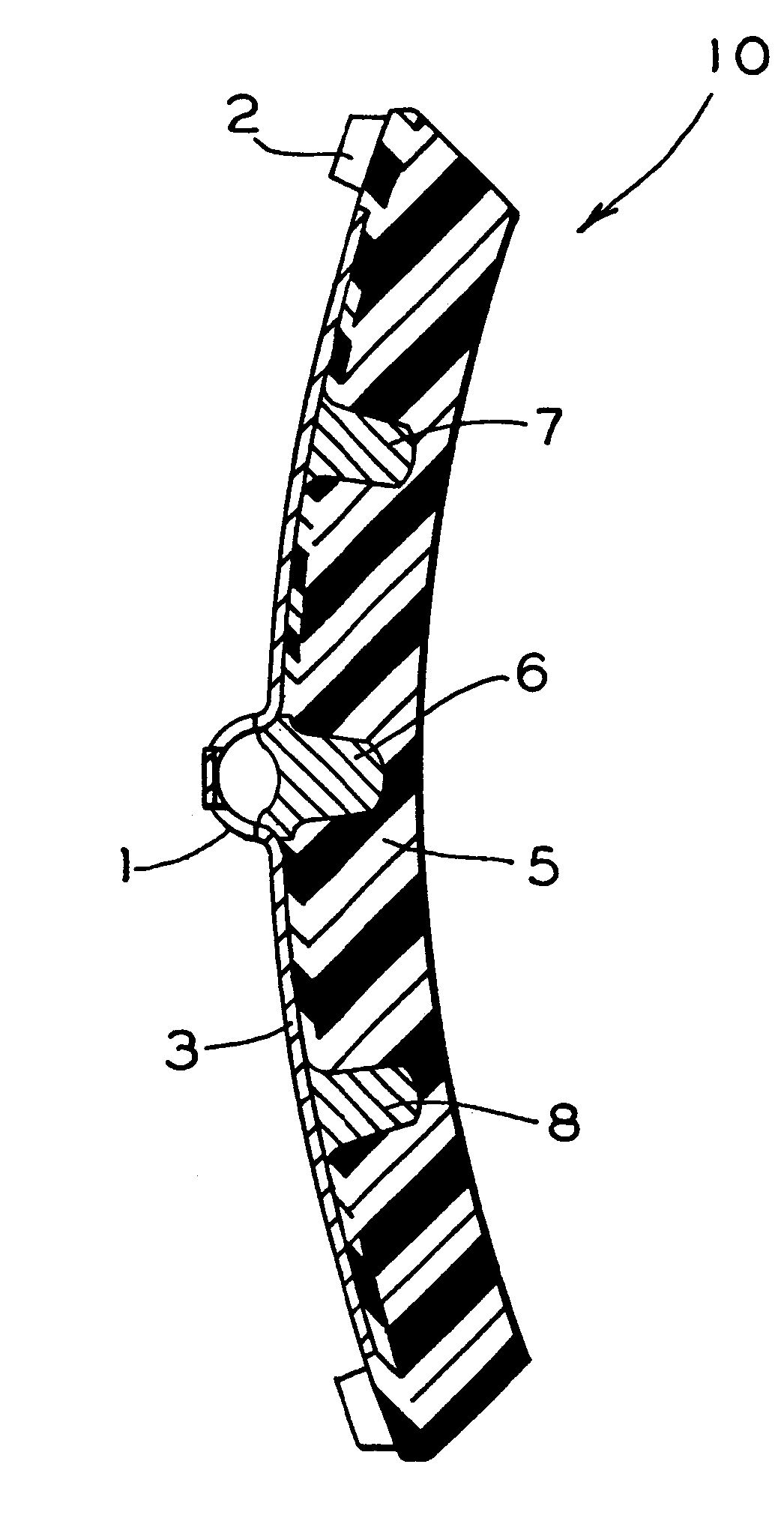
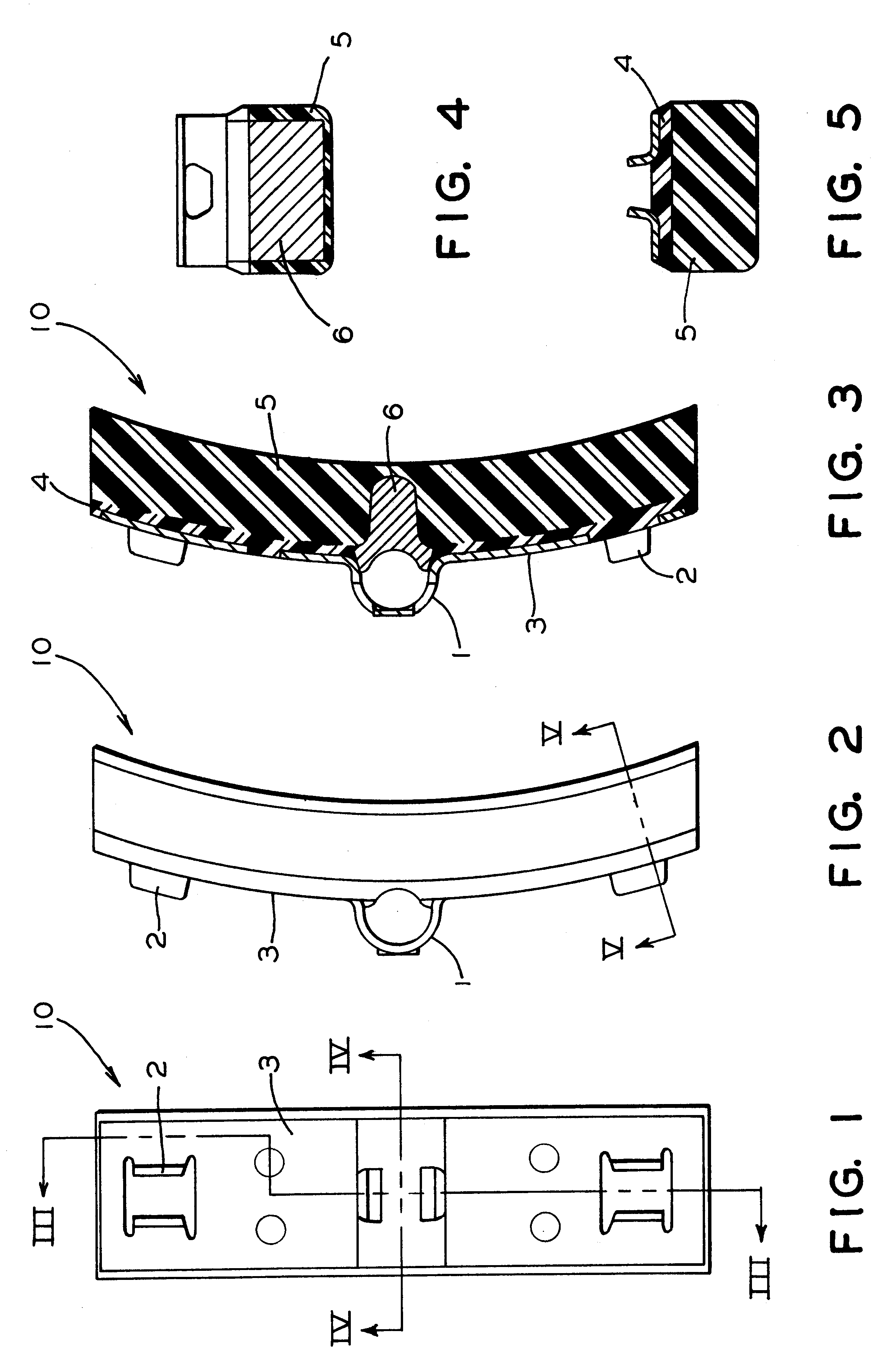
the invention is illustrated in FIGS. 6 to 10. As is evident in FIG. 7, there are two discrete inserts of such second friction material 7 and 8. In this embodiment of the invention such discrete inserts 7 and 8 are each disposed at a point that is intermediate between the ends of such brake shoe and a center point of such brake shoe. In a presently preferred embodiment of the invention such discrete inserts 7 and 8 are substantially equidistant from such center point of the brake shoe and the ends of the brake shoe. Such discrete inserts 7 and 8 of such second friction material are also bonded to such backing plate. Also in a presently preferred embodiment such discrete inserts 7 and 8 are welded to backing plate 3.

Reference in now made to FIGS. 11 through 15. Illustrated therein is a third embodiment of the invention. As is evident in FIGS. 13 and 14, there are three discrete inserts 6, 7, and 8 of such second friction material. Again as is evident such three discrete inserts 6, 7,...


PUM


Abstract

A composition brake shoe for use on a railway vehicle for reconditioning a wheel tread surface during a normal braking application on such railway vehicle is provided. The composition brake shoe includes a backing plate having a stirrup and a brake surface having a predetermined configuration and a predetermined surface area. It further includes a first friction type composition material extending over the surface area of such brake surface of such composition brake shoe. The composition brake shoe further contains a second friction type material, formed as at least one discrete insert, having a predetermined shape and molded into such first friction type composition material. Such second friction type material initially being completely embedded within such first friction type composition material. One surface of such at least one discrete insert being incrementally exposed as such first friction type composition material is eroded away due to frictional engagement with such wheel tread surface during normal braking operations, such second friction type material exhibiting greater abrasive properties than such first friction type composition material. Such at least one discrete insert of such second friction type material is bonded to such backing plate.

Description

The present invention relates, in general, to railway vehicle type braking equipment and, more particularly, this invention relates to a composition type brake shoe for use in a railway type vehicle brake system and, even still more specifically, the invention relates to an improved brake shoe member with an insert of aggressive high friction material for removing defects of the tread surface of a wheel.Prior to the conception and subsequent development of this invention, it is generally well known in the art to use various type brake shoes having different compositions to achieve quite specific braking requirements. For example, these compositions may include cast iron and various other type friction materials that are specifically formulated for a number of predetermined applications.It is further well recognized, in the brake shoe art, that these various types of friction material will normally exhibit a number of uniquely different friction characteristics. Such friction charact...

Claims


Application Information

Patent Timeline
IPC IPC(8): F16D65/04F16D65/06F16D65/00F16D69/00
CPCF16D65/0037F16D65/062F16D2069/002
Inventor SHUTE, BRUCE W.KAHR, JOSEPH C.
Owner RFPC HLDG CORP
Learn More