
Electrical power generation system having means for managing the discharging and recharging of metal fuel contained within a network of metal-air fuel cell battery subsystems

a technology of electric power generation system and fuel cell battery, which is applied in the direction of fuel cells, secondary cells, electric devices, etc., can solve the problems of special fuel handling procedures, fuel inefficiency, and hydrogen as a fuel source in automobiles

Inactive Publication Date: 2001-05-29
REVEO
View PDF63 Cites 55 Cited by
  • Summary
  • Abstract
  • Description
  • Claims
  • Application Information

AI Technical Summary

Benefits of technology

Accordingly, a primary object of the present invention is to provide an improved method of and system for generating electrical power from metal-air FCB systems so that the peak power requirements of electrical loads connected thereto can be met in a satisfactory manner while overcoming the shortcomings and limitations of prior art technologies.
Another object of the present invention is to provide such a system, wherein metal-fuel contained within each of the metal-air FCB subsystems is realized in the form of a supply of metal-fuel tape which can be transported through its discharging head assembly in a bi-directional manner while the availability of metal-fuel therealong is automatically managed in order to improve the performance of the system.
Another object of the present invention is to provide such a system, wherein metal-fuel tape can be transported through its recharging head assembly in a bi-directional manner while the presence of metal-oxide therealong is automatically managed in order to improve the performance of the system during the recharging operations carried out within respective metal-air FCB subsystems.

Problems solved by technology

While this technique appears promising in space applications, the use of hydrogen as a fuel source in automobiles presents numerous problems including, for example, the volatility of hydrogen, special fuel-handling procedures, fuel inefficiency, and the like.
With such technology, however, it is not possible to construct a vehicle that has the capacity to travel long distances without recharging its electric batteries.
Factors which contribute to such limitations include the weight of the batteries, and the low volumetric power densities associated with conventional battery technology.
Presently, this approach is not feasible due to the inefficiencies of photo-voltaic cells and energy storage capacities of commercial storage batteries.
Despite such promise offered by metal-air FCB technology, such technology is not without its problems.
However, when electrical loading is light, the metal-fuel tape is only partially consumed and electrical power inefficiently generated.
Notably, the use of this power control method over time will result in a rapid depletion of the metal-fuel in certain of the metal-air FCB subsystems that have been frequently operated, but not in other metal-air FCB subsystems that have been operated less frequently.
Then when the power demanded by the load increases to its peak power demand value, the resulting FCB system will lack the capacity to generate a sufficient amount of output power to meet the peak power requirements of the electrical load.

Method used


Image

  • Electrical power generation system having means for managing the discharging and recharging of metal fuel contained within a network of metal-air fuel cell battery subsystems
  • Electrical power generation system having means for managing the discharging and recharging of metal fuel contained within a network of metal-air fuel cell battery subsystems
  • Electrical power generation system having means for managing the discharging and recharging of metal fuel contained within a network of metal-air fuel cell battery subsystems

Examples


Embodiment Construction

Of the Present Invention should be read in conjunction with the accompanying Drawings, wherein:

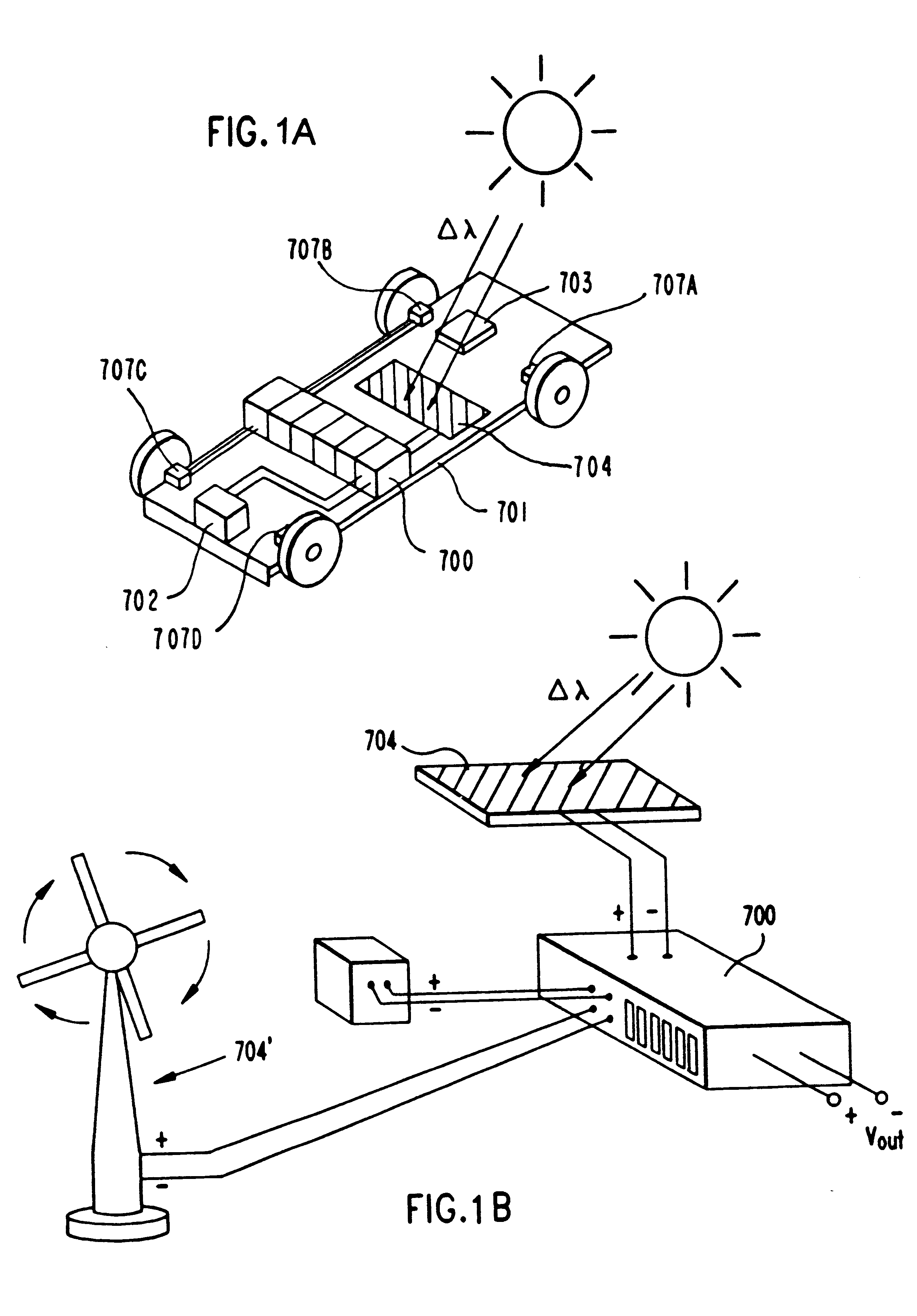
FIG. 1A is a schematic representation of a transportation vehicle, wherein the electrical power generation system of the present invention is provided for the purpose of generating and supplying electrical power to electrically-driven motors coupled to the wheels of the vehicle, and wherein auxiliary and hybrid power sources are provided for recharging metal-fuel within the FCB subsystems thereof;

FIG. 1B is a schematic representation of the electrical power generation system of the present invention realized as a stationary electrical power plant having auxiliary and hybrid power sources for recharging metal-fuel within the FCB subsystems thereof;

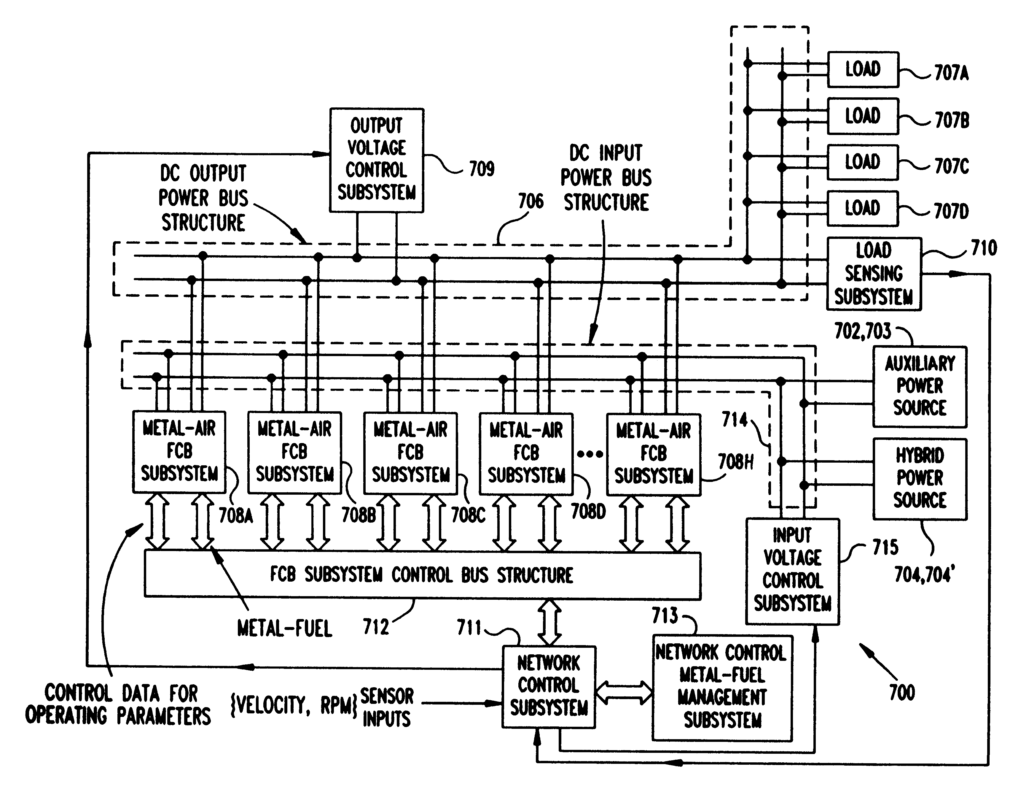
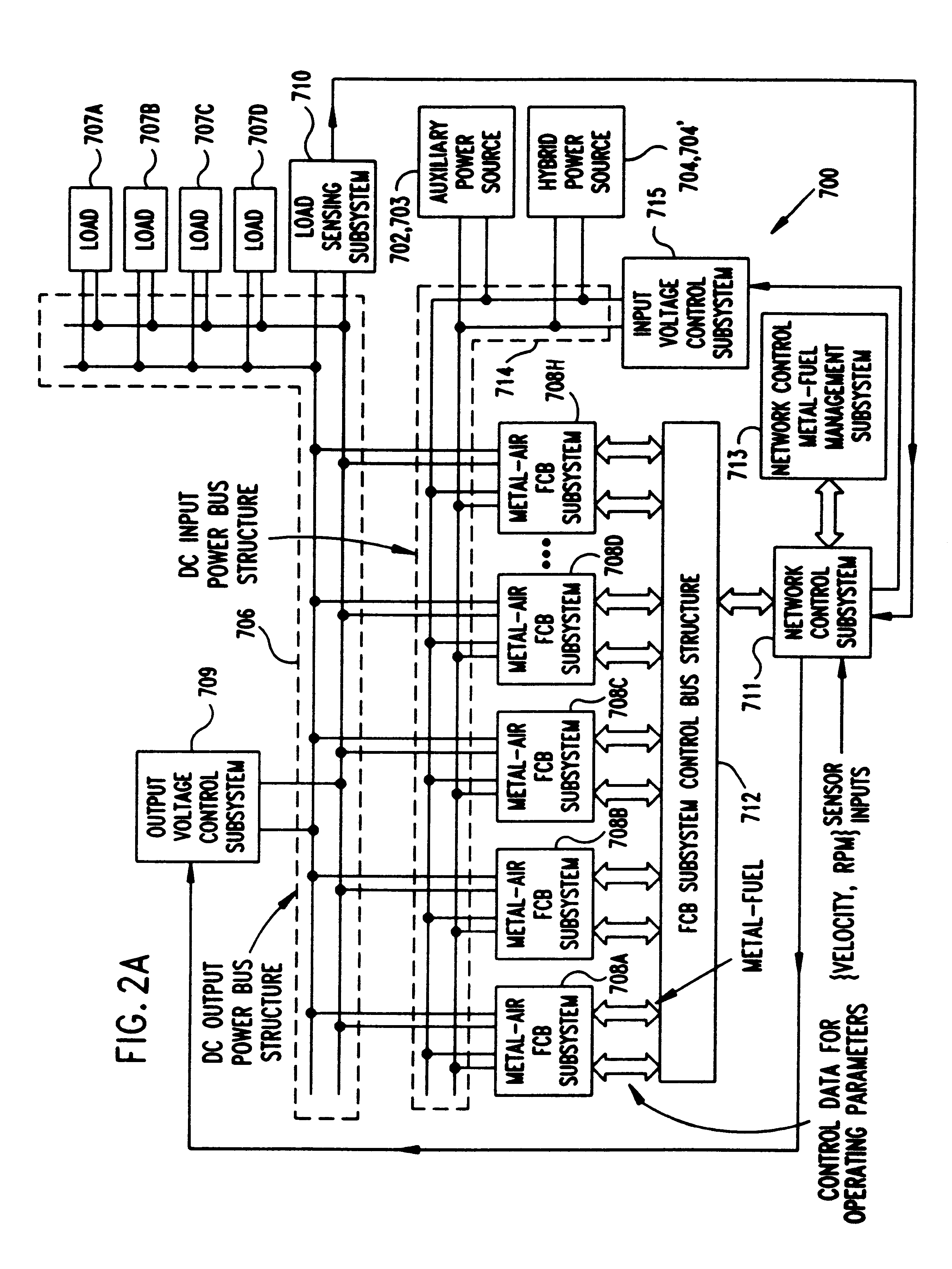
FIG. 2A is a schematic representation of the electrical power generation system of a first illustrative embodiment, wherein a network of metal-air FCB subsystems are operably connected to a DC power bus structure and controlled by a network contro...


PUM

PropertyMeasurementUnit
degree of porosityaaaaaaaaaa
voltageaaaaaaaaaa
voltagesaaaaaaaaaa

Abstract

Disclosed is an electrical power generation system comprised of a network of metal-air fuel cell battery (FCB) subsystems connected to an output power bus structure and controlled by a network control subsystem. The operation of each metal-air FCB subsystem is controlled so that, on the average, the amount of metal-fuel in each of the FCB subsystem is substantially the same, regardless of the total amount of metal-fuel remaining within the system available for electrical power generation. The electrical power generation system can be used as an electrical power plant that can be installed in virtually any system, device or environment in which there is a need to satisfy the peak power demand of an electrical load (e.g. motor, appliance, machinery, tools, etc.) independent of the total amount of metal-fuel remaining within the system. The system is provided with a network-based metal-fuel management subsystem adapted for use in managing the discharging and recharging of metal-fuel in the system in an efficient manner. In the illustrative embodiment, the electrical power generation system is embedded within an automotive vehicle that is provided with hybrid types of electrical power generating sources, as well as an auxiliary power source, for providing electrical power to the input bus structure for carrying out recharging operations.

Description

1. Field of the InventionThe present invention relates to an improved way of and means for producing electrical power from a network of metal-air Fuel Cell Battery (FCB) subsystems so that the peak power requirements of an electrical load (e.g. motor, appliance, machinery, tools, etc.) can be satisfied independent of the total amount of metal-fuel remaining within the system at any instant of time.2. Description of the Prior ArtThere is an increasing demand for electrically-powered vehicles in our society. As such, numerous methods have been proposed for supplying electric power to such electric vehicles.One method of providing electrical power to such vehicles involves using hydrogen-based fuel cells. While this technique appears promising in space applications, the use of hydrogen as a fuel source in automobiles presents numerous problems including, for example, the volatility of hydrogen, special fuel-handling procedures, fuel inefficiency, and the like.Alternative approaches to ...

Claims


Application Information

Patent Timeline
Patent Type & Authority Patents(United States)
IPC IPC(8): H01M2/02H01M12/06H01M10/42H01M10/48H01M12/00H01M10/46H01M8/04H01M2/12H01M4/00H01M4/02H01M4/70
CPCH01M6/5011H01M8/184H01M8/186H01M8/22H01M10/4214H01M12/06H01M12/08H02J7/00H01M4/42H01M2/1673Y02E60/528H01M4/8605H01M10/44H01M2004/024H01M2300/0085B60L53/00B60L53/51B60L53/52B60L53/54H01M50/46Y02E60/10Y02E60/50Y02T10/70Y02T10/7072Y02T90/12Y02T90/14
Inventor FARIS, SADEG M.TSAI, TSEPIN
Owner REVEO
Learn More