
Wheel and tension spoke system

a technology of tension spokes and spokes, which is applied to the field of wheels, can solve the problems of system lack of sufficient durability for effective vehicle use, and achieve the effect of sufficient durability

Inactive Publication Date: 2001-05-29
COMPOSITES DESIGN SERVICES
View PDF17 Cites 55 Cited by
  • Summary
  • Abstract
  • Description
  • Claims
  • Application Information

AI Technical Summary

Benefits of technology

The path of each shaft may be substantially aligned with the center of a rim pivot and a hub pivot so that a tension along the shaft will not produce a moment about the rim pivot or the hub pivot. Because tension in a shaft will not produce such a moment, the shaft will not be subjected to significant bending or shear stresses. Accordingly, the durability and strength of each shaft is increased. This is especially true if the spokes are composite spokes that are strong and durable in tension.
The tensioning system may include plural tensioning mechanisms. Each tensioning mechanism may include a clevis with a base attached to the hub and two arms extending from the base, a reaction pin extending between the two arms, a hub attachment pin extending through a central portion of a vertex, a pusher pad engaging the hub attachment pin, and a tension adjusting screw engaging the reaction pin and biasing the pusher pad so as to bias the hub attachment pin and the vertex, thereby tensioning the continuous spoke. Each tensioning mechanism may be located near the hub so that the polar moment of inertia of the wheel is minimized.

Problems solved by technology

Some such systems have lacked sufficient durability for effective use in vehicles because the connections to the rim and the hub are not sufficiently durable or strong.

Method used


Image

  • Wheel and tension spoke system
  • Wheel and tension spoke system
  • Wheel and tension spoke system

Examples


Embodiment Construction

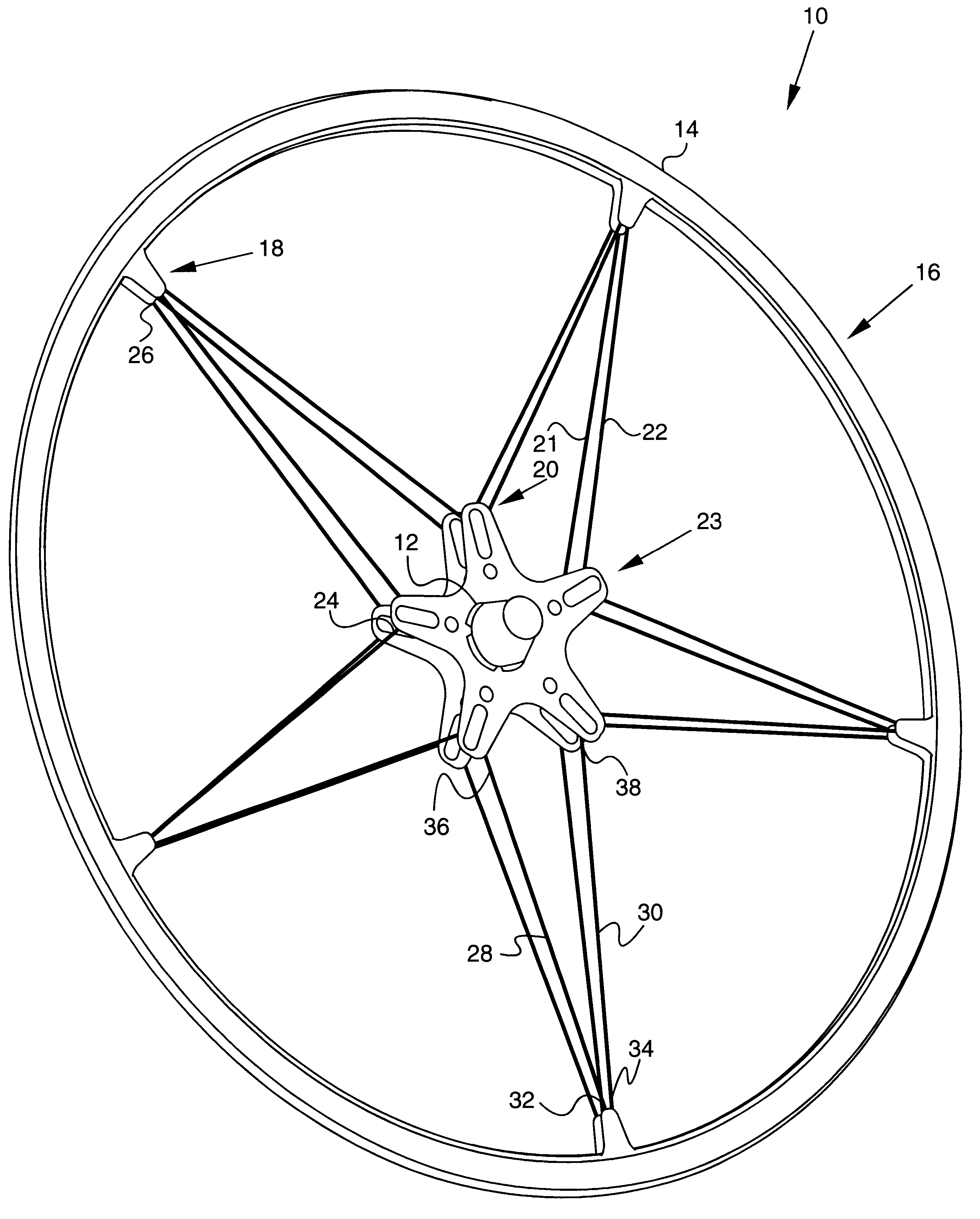
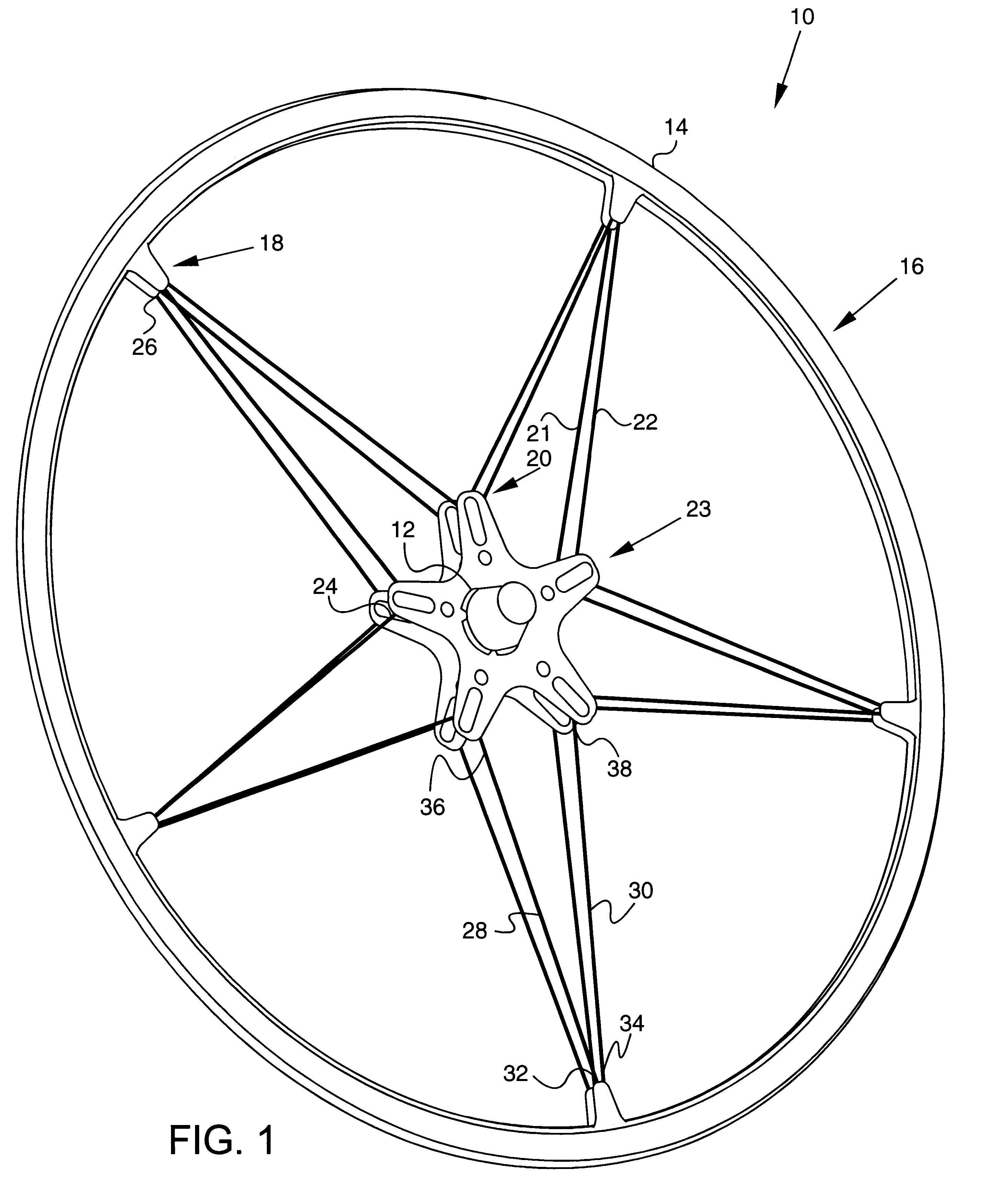
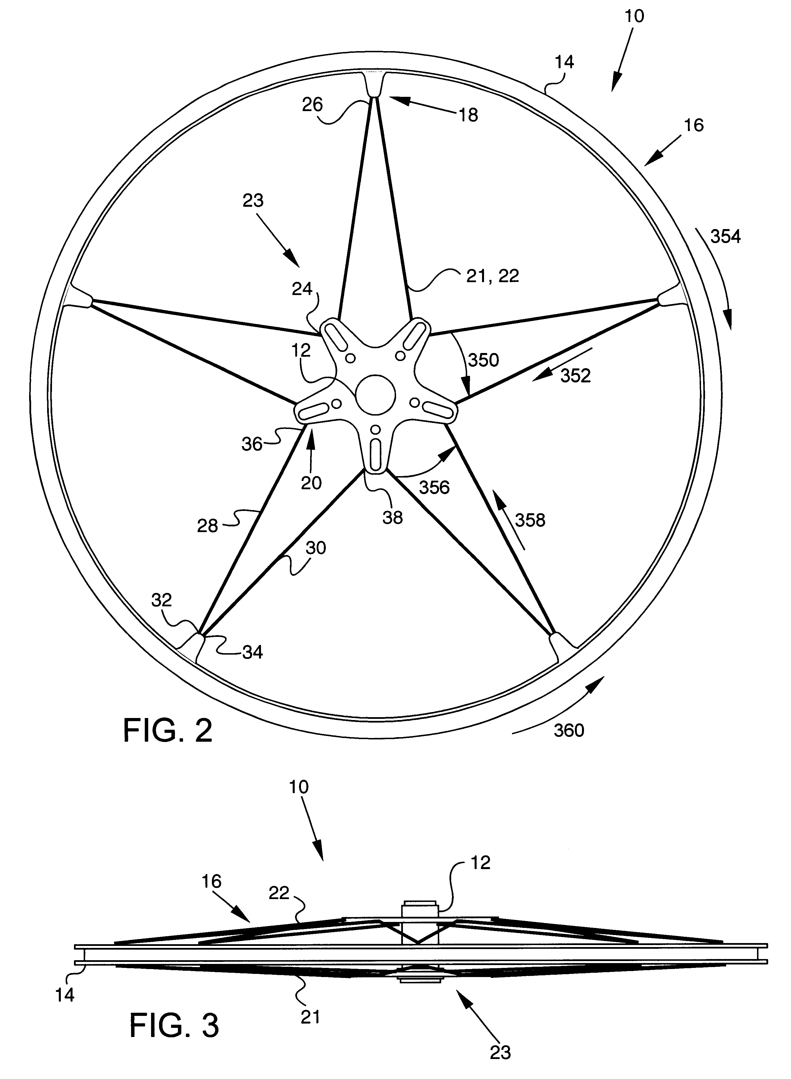
Referring to FIG. 1-3, a wheel 10, such as a bike wheel, includes a hub 12 that rotates about a rotational axis, a rim 14, and a spoke system 16 that keeps rim 14 stationary relative to hub 12 by transmitting force and torque from between rim 14 and hub 12. Spoke system 16 preferably includes at least three rim pivots 18 and at least three hub pivots 20 that are located radially inwardly from rim pivots 18 and that are circumferentially offset from rim pivots 18. Spoke system 16 also preferably includes a continuous spoke 21, 22, and a tensioning system 23 for tensioning the continuous spoke 21, 22.

Each continuous spoke 21, 22 has at least three inner vertices 24 each connected to a hub pivot 20, at least three outer vertices 26 each connected to a rim pivot 18, and shafts 28, 30. Each shaft 28, 30 extends from a rim pivot 18 to a corresponding hub pivot 20 (as can be seen in FIG. 1, each rim pivot 18 can correspond to more than one hub pivot 20, and each hub pivot 20 can correspond...


PUM


Abstract

A spoke system includes at least three rim pivots, at least three hub pivots, and plural shafts each extending along a substantially linear path between a rim pivot and a hub pivot, each path being substantially aligned with the center of a rim pivot and the center of a hub pivot. Each shaft includes an integral rim end forming a loop around a rim pivot and an integral hub end forming a loop around a hub pivot. The present invention also includes a tensioning system for biasing the inner vertices away from the outer vertices, thereby tensioning the continuous spoke. The path of each shaft may be substantially aligned with the center of a rim pivot and the center of a hub pivot so that a tension along the length of the shaft will not produce a moment about the rim pivot or the hub pivot. The tensioning system may include plural tensioning mechanisms, with each tensioning mechanism including a clevis with a base attached to the hub and two arms extending from the base, a reaction pin extending between the two arms, a hub attachment pin extending through a central portion of a vertex, a pusher pad engaging the hub attachment pin, and a tension adjusting screw engaging the reaction pin and biasing the pusher pad so as to bias the hub attachment pin and the vertex, thereby tensioning the shafts.

Description

1. Technical FieldThis invention generally relates to wheels, and more specifically relates to spoke systems for wheels.2. Background ArtA typical wheel, such as a bicycle wheel, includes a rim, a hub, and a spoke system for keeping the rim stationary relative to the hub. Spoke systems have traditionally been of two main types: compression spoke systems, and tension spoke systems. Some spoke systems use both compression and tension. Compression spoke systems and systems that combine compression or tension and shear typically require weightier spokes than tension spoke systems to prevent buckling of the spokes. Accordingly, tension spoke systems are common because they allow for thinner, and thus lighter, spokes. Such systems have typically used metal rods, such as steel rods, for spokes. Such rods do not have extremely high tensile strengths for their weight, but they are easily connected at their ends to the rim and the hub.Some have tried to use composites in spoke systems. Some s...

Claims


Application Information

Patent Timeline
IPC IPC(8): B60B21/06B60B21/00B60B1/00B60B1/04
CPCB60B1/003B60B1/0207B60B1/0223B60B1/0261B60B1/0276B60B1/041B60B1/042B60B21/062
Inventor FORSYTHE, PAUL D.HOON, DOUGLAS M.
Owner COMPOSITES DESIGN SERVICES
Learn More