Visualization system and method for a web inspection assembly

Inactive Publication Date: 2001-05-22
WEBVIEW
View PDF27 Cites 21 Cited by
  • Summary
  • Abstract
  • Description
  • Claims
  • Application Information

AI Technical Summary

Benefits of technology

Accordingly, it is an object of the present invention to provide a visualization subsystem and method for a web inspection assembly which operates more efficiently and in a hands-free manner.
Still another object of the present invention is to provide a visualization subsystem and method for a web inspection assembly which increases the resolution of the anomaly on the monitor.
Another object of the present invention is to provide a visualization subsystem and method for a web inspection assembly which reduces the amount of storage space required to store an image of the detected surface anomaly.
It is a further object of the present invention is to provide a visualization subsystem and method for a web inspection assembly which can be easily retrofit to any type of line scan device, camera, laser scanner or the like.
Still yet another object of the present invention is to provide a visualization subsystem and method for a web inspection assembly which reduces operator error.
Still a further object of the present invention to provide a visualization system for a web inspection assembly which is durable, compact, easy to maintain, has a minimum number of components, cost effective to manufacture, and is easy to use by moderately skilled personnel.

Problems solved by technology

Due to the high roll speeds of the moving web, real-time visualization of a detected anomaly is difficult to attain.
Hence, these designs are relatively labor intensive to operate since the operator must devote their operative attention entirely to the viewing the monitor to identify a surface anomaly.
Should the operator fail to observe an anomaly on the display screen, for whatever reason, the defect may pass undetected.
One problem associated with these systems is that the visualization techniques are performed in real-time scrolling illustrations on the monitor until a defect is identified.
Stopping a high speed moving web, however, is a difficult task since the web is a continuous process manufacturing.
Accordingly, the costs associated with stopping the web are substantial.
On the other hand, pausing the real-time scrolling to pan in on the defect may also be problematic since the web continues to move.
Not only is this technique labor intensive, but should there be multiple defects when the operator is devoting his attention to viewing the first identified anomaly on the monitor, these other defects may pass through the visualization system undetected.
Further, visual resolution is often poor due in-part to the data compression techniques employed.
Finally, while some of these designs include storage devices to store records of the web inspection, the amount of storage space required to reproduce an image of a single defect is substantial since these designs are only capable of storing full frames.
Accordingly, a substantial amount of unnecessary storage space is required, because each defect would require 262,144 bytes (i.e., 512.times.512).

Method used


Image

  • Visualization system and method for a web inspection assembly
  • Visualization system and method for a web inspection assembly
  • Visualization system and method for a web inspection assembly

Examples


Embodiment Construction

While the present invention will be described with reference to a few specific embodiments, the description is illustrative of the invention and is not to be construed as limiting the invention. Various modifications to the present invention can be made to the preferred embodiments by those skilled in the art without departing from the true spirit and scope of the invention as defined by the appended claims. It will be noted here that for a better understanding, like components are designated by like reference numerals throughout the various figures.

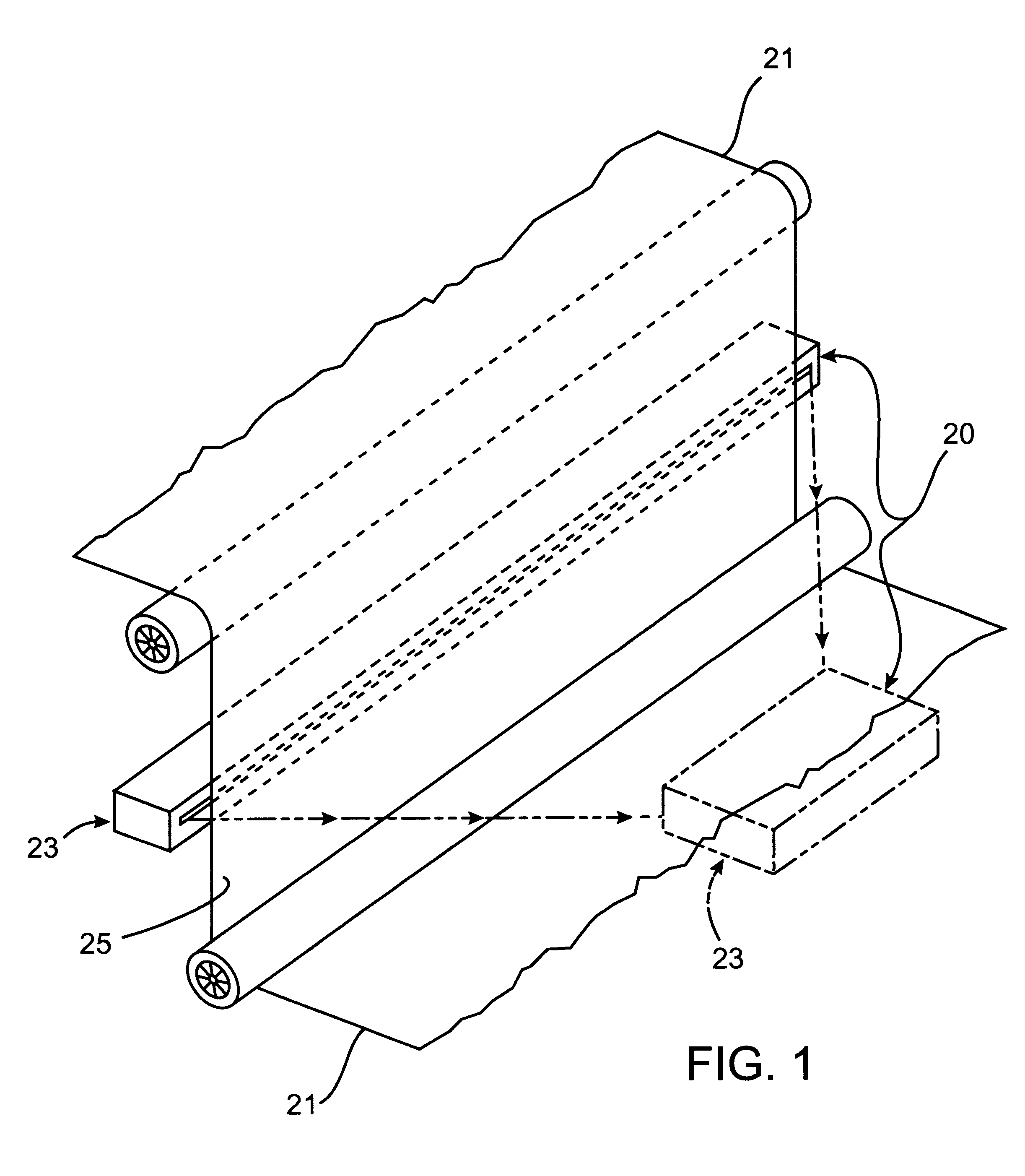
Attention is now directed to FIGS. 1-3 where a web inspection apparatus, generally designated 20, is illustrated for use in identifying surface anomalies on a moving material web 21. The web inspection apparatus in accordance with the present invention includes a scanning device 22 and data processing circuitry, generally designated 23, for monitoring and analyzing the output data of the scanning device 22. The scanning device is configu...


PUM


Abstract

A web inspection apparatus (20) and method for use in identifying surface anomalies (26) on a moving material web (21) including a scanning device (22) and data processing circuitry (23) for monitoring and analyzing the output data of the scanning device (22). The scanning device (22) is configured to continuously scan a surface (25) of the moving web (21) and generates output data representative of the surface of the web. The data processing circuitry (23) is responsive to selected output data representing at least one type of surface anomaly (26) such that Region Of Interest (ROI) data are automatically recorded. This ROI data represents the detected anomaly (26) and an immediate surrounding region (27) including the detected anomaly. The hands-free data processing circuitry (23) continuously monitors and analyzes the output data generated by the scanning device (22) while the ROI data is being stored. A storage device (28) is coupled to the data processing circuitry (23) for storage of the selected ROI data.

Description

The present invention relates, generally, to web inspection assemblies and, more particularly, relates to visualization systems for high speed, high resolution web inspection assemblies.In recent years, considerable effort has been directed toward on-line web inspection to enhance the uniform quality of material webs, such as paper, glass, plastic, textiles, metallic sheets, fiberglass and sheet substrates. These web inspection assemblies are capable of high speed, high resolution detection and classification of surface imperfections in continuously manufactured products at rates in excess of 500 inches per second. Such surface imperfections include tears, through-holes, abrasions and scattering imperfections, impurities preventing local processing, stains and absorbing imperfections, pinch marks, thickness imperfections, and other far side and near side imperfections.Web inspection assemblies often include an illumination source generating a point of light or a strip of light, and ...

Claims


Application Information

Patent Timeline
IPC IPC(8): G01N21/88G01N21/89
CPCG01N21/8901G01N21/8851G01N2021/8896
Inventor HO, MORRIS D.
Owner WEBVIEW
Why Eureka
Try Eureka