
Magnetic actuation urethral valve

Inactive Publication Date: 2001-05-22
HE HONGPING +1
View PDF5 Cites 103 Cited by
  • Summary
  • Abstract
  • Description
  • Claims
  • Application Information

AI Technical Summary

Benefits of technology

To get strong force is very important to make sure the operation of the valve can be reliably performed and the size of the valve body can be reduced. That is the basic point to make this valve reliable, and easy to install or remove.
The limited range of the thread area of the actuation axle and the control nut are designed to prevent the valve from getting stuck when the threaded hole and the control nut is over-tightened. The springs at each side of the control nut are for the purpose of being able to secure the threaded portion of the actuation axle going back into the control nut after the threaded portion runs out of the control nut in both directions.

Problems solved by technology

Urinary incontinence is a common and serious problem that may be caused by old age, some forms of neurological dysfunction or injuries, or prostate and bladder surgeries.
Such problem is hard to treat or, generally, incurable.
Patients suffering from this problem not only may experience discomfort and embarrassment, but also may lose some normal human activities.
Use of indwelling catheters and associated bags often leads to infections of the bladder because the catheter provides a direct passage to microorganisms into the human body.
Use of diapers is uncomfortable and embarrassing.
Use of artificial urethral sphincters needs surgical implantation that is expensive, complicated, and has a low success rate, sometimes leading to serious complications.
The structure of this device is complicated while its size is considerably large.
Due to the weak pulling force from direct attraction, it does not work reliably and increases the possibility of malfunction of the unit and consequential repair or replacement.
Furthermore, its physical size presents extreme difficulties in insertion and removal.
One problem of this design is that the valve might leak when the patient moves tremendously such as running or jumping due to the vibration of relatively long actuator rod with a magnet on its top.
Another problem is the possibility of formation of bladder stones caused by a foreign object, which is the extending actuator rod inside the bladder.

Method used


Image

  • Magnetic actuation urethral valve
  • Magnetic actuation urethral valve
  • Magnetic actuation urethral valve

Examples


Embodiment Construction

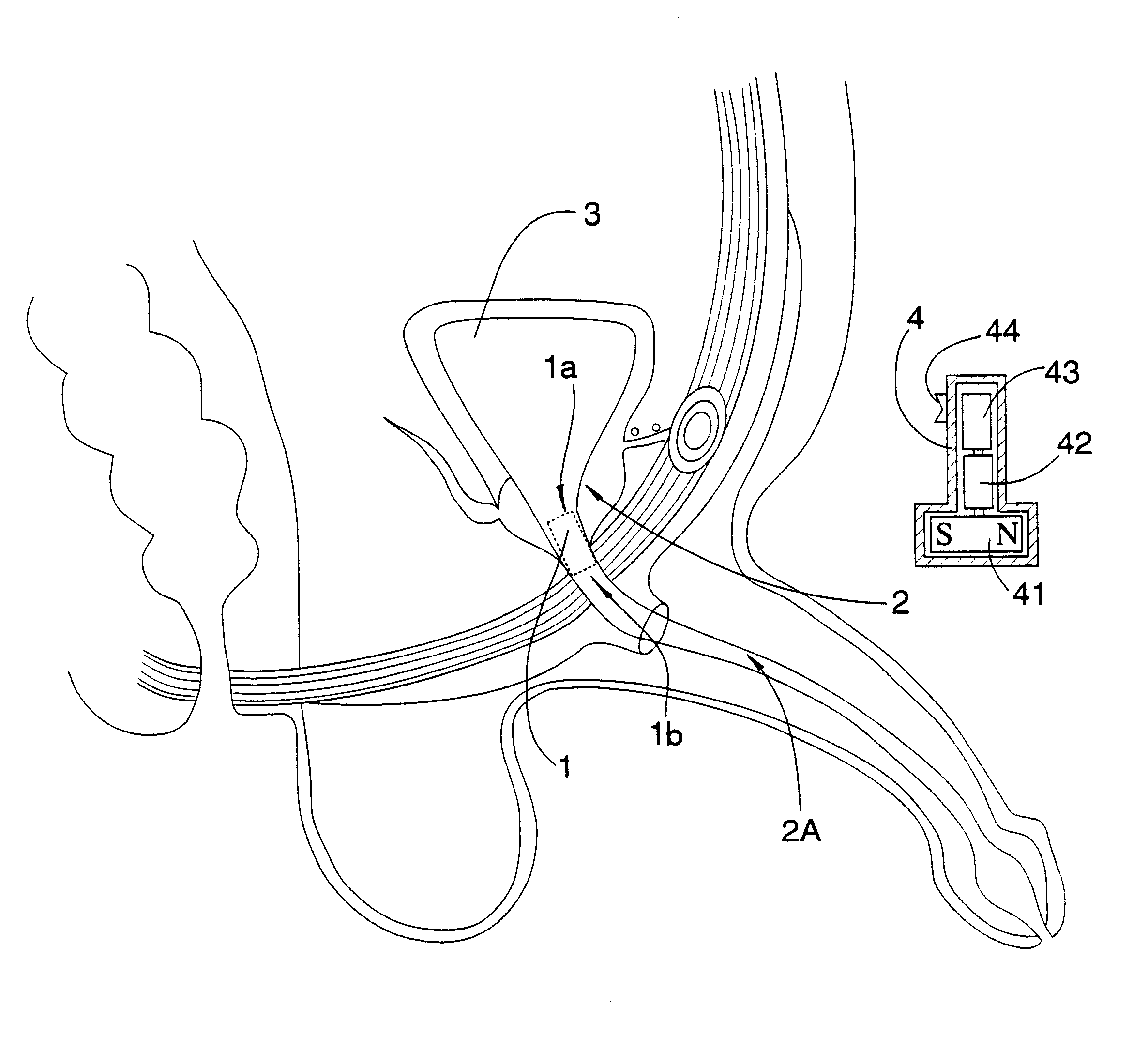
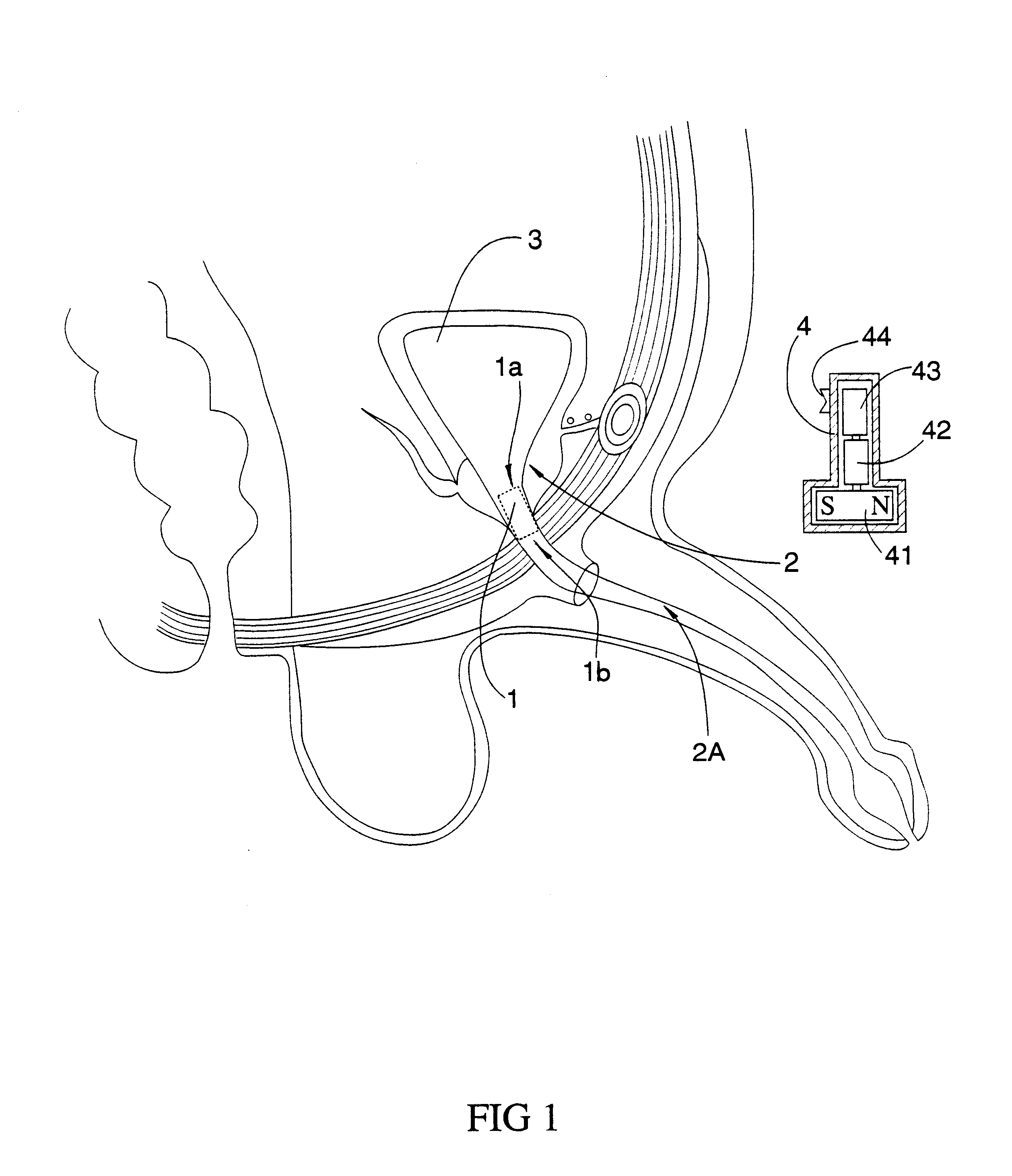
Referring FIG. 1 of the drawings, a magnetic actuation urethral valve 1 according to a preferable embodiment of the present invention is placed in the prostate portion 2 of a male urethra 2A with a proximal end 1a thereof opening to a bladder 3, wherein a magnetic controller 4 turns to produce a rotating magnetic field to drive the magnetic actuation urethral valve 1 between an open position and a close position. FIG. 2 illustrates where the magnetic actuation urethral valve 1 should be placed in a female urethra 2B.

As shown in FIGS. 1 and 2, the magnetic controller 4 comprises a strong permanent magnet 41 and a geared DC motor 42. The DC motor 42 turns the magnet 41 clockwise or counterclockwise by exchanging the positive and negative connections to a power source 43 through a switch 44 of the controller 4, thus produces the rotation of the controlling magnetic field in both directions to drive the magnet rotor, which opens the valve and lets out the urine or shuts it. The gears ar...


PUM


Abstract

A magnetic actuation urethral valve is adapted for inserting into the urethra of a patient who suffering from urinary incontinence in order to recover control of urine flow. The valve member is driven by a magnet rotor which is magnetically actuated by a rotating magnetic field generated from a controller outside the body. There is also an actuation device for the user to discharge by inserting an indwelling catheter into the valve in case the valve does not work for any reason.

Description

BACKGROUND OF THE PRESENT INVENTION1. Field of the Present InventionThe present invention relates to urethral valves, and more particularly to a magnetic actuation urethral valve adapted for inserting into the urethra of a patient who suffering from urinary incontinence in order to recover control of urine flow.2. Description of Related ArtsUrinary incontinence is a common and serious problem that may be caused by old age, some forms of neurological dysfunction or injuries, or prostate and bladder surgeries. Such problem is hard to treat or, generally, incurable. Patients suffering from this problem not only may experience discomfort and embarrassment, but also may lose some normal human activities.Many efforts have been taken to solve this problem. Use of indwelling catheters and associated bags often leads to infections of the bladder because the catheter provides a direct passage to microorganisms into the human body. Use of diapers is uncomfortable and embarrassing. Use of artif...

Claims


Application Information

Patent Timeline
IPC IPC(8): A61F2/00
CPCA61F2/0018
Inventor HE, HONGPINGHE, MING
Owner HE HONGPING
Learn More