
Water saving mechanism for shower device

a shower device and water saving technology, applied in mechanical devices, transportation and packaging, valve types, etc., can solve problems such as out-of-orderness and problems in the water saving mechanism of conventional shower devices

Inactive Publication Date: 2001-05-22
DAE YONG
View PDF9 Cites 15 Cited by
  • Summary
  • Abstract
  • Description
  • Claims
  • Application Information

AI Technical Summary

Benefits of technology

According to an aspect of the present invention, there is provided a water saving mechanism for a shower device comprising: a ball valve taking a ball shape; a body having a valve space into which the ball valve is inserted and having an exit hole on the one side thereof, the exit hole having a smaller diameter than the ball valve; a ball valve moving member adapted to be coupled to the valve space in the direction opposite to the exit hole of the body and having a moving hole into which the ball valve is movably inserted on the interior thereof to thereby limit the moving range of the ball valve; and an operating member adapted to be assembled to be movable forwardly / backwardly in a radial direction on the one side of the peripheral surface of the body and / or the ball valve moving member and for moving the ball valve towards the ball valve moving member by the advancement to the exit hole of the body.
According to another aspect of the present invention, there is provided a shower head including a water saving mechanism comprising: a first head body having a connecting part connected to a shower hose on the one end portion thereof; a second head body adapted to be assembled with the first head body and having a passage and an assembling space in the interior thereof and a plurality of spray holes formed on the end portion opposite to the connecting part of the first head body; a ball valve taking a ball shape; a body adapted to be inserted into the assembling space formed by means of the first and second head bodies and having a valve space into which the ball valve is inserted and having an exit hole on the one side thereof, the exit hole having a smaller diameter than the ball valve; a ball valve moving member adapted to be coupled to the valve space in the direction opposite to the exit hole of the body and having a moving hole into which the ball valve is movably inserted on the interior thereof to thereby limit the moving range of the ball valve; and an operating member adapted to be assembled to be movable forwardly backwardly in a radial direction of the exit hole of the body on the one side of the peripheral surface of the body and by passing the first head body or the second head body and for moving the ball valve towards the ball valve moving member by the advancement to the exit hole of the body.

Problems solved by technology

However, from environmental and economical points of view, the conventional shower device contains some problems to be solved.
Unfortunately, on the other hand, the water saving structure which is adapted to the conventional shower device has the following disadvantages: firstly, it is constructed in a complex manner; secondly, it is expensive; and thirdly, it often gets out of order.
Moreover, since the conventional water saving structure can not be applicable to the existing shower device, there is an inconvenience that the existing shower device already installed and used should be exchanged into a new one so as to introduce the water saving structure.

Method used


Image

  • Water saving mechanism for shower device
  • Water saving mechanism for shower device
  • Water saving mechanism for shower device

Examples


Embodiment Construction

Reference will now be made in detail to the preferred embodiments of the present invention, examples of which are illustrated in the accompanying drawings.

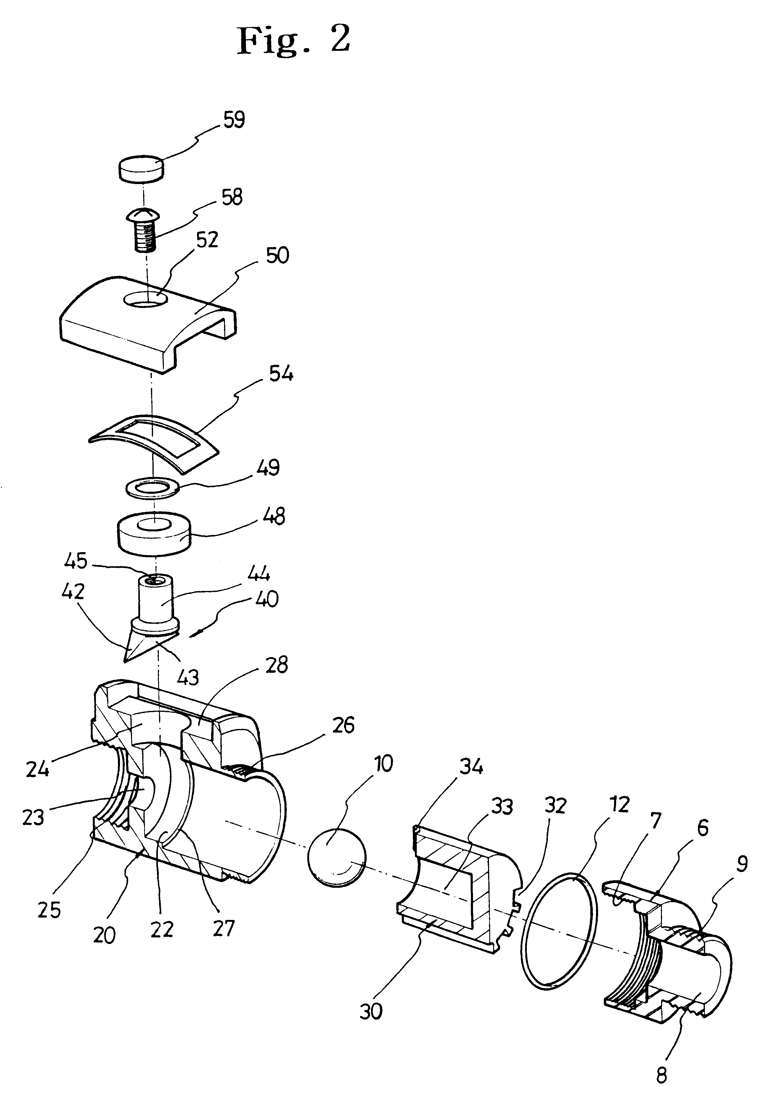
FIGS. 1 to 3 show a water saving mechanism for a shower device according to a preferred embodiment of the present invention.

In construction, the water saving mechanism includes: a ball valve 10 taking a ball shape; a body 20 having a valve space 22 into which the ball valve 10 is inserted and having an exit hole 23 on the one side thereof, the exit hole 23 having a smaller diameter than the ball valve 10; a ball valve moving member 30 adapted to be coupled to the valve space 22 in the direction opposite to the exit hole 23 of the body 20 and having a moving hole 33 into which the ball valve 10 is movably inserted on the interior thereof to thereby limit the moving range of the ball valve 10; and an operating member 40 adapted to be assembled to be movable forwardly / backwardly in a radial direction on the one side of the peripheral...


PUM


Abstract

A water saving mechanism is assembled with a shower device and is simply constructed in such a manner that supply of water is executed by the pressing of a push member and discharge of water is cut by the inclination of a shower head in a downward direction. The water saving mechanism for the shower device includes: a ball valve taking a ball shape; a body having a valve space into which the ball valve is inserted and having an exit hole on the one side thereof, the exit hole having a smaller diameter than the ball valve; a ball valve moving member adapted to be coupled to the valve space in the direction opposite to the exit hole of the body and having a moving hole into which the ball valve is movably inserted on the interior thereof to thereby limit the moving range of the ball valve; and an operating member adapted to be assembled to be movable forwardly / backwardly in a radial direction on the one side of the peripheral surface of the body and / or the ball valve moving member and for moving the ball valve towards the ball valve moving member by the advancement to the exit hole of the body.

Description

(a) Field of the InventionThe present invention relates to a water saving mechanism for a shower device which is assembled with the shower device and is simply constructed, by using a ball valve, in such a manner that supply of water is executed by the pressing of a push member and discharge of water is stopped by the inclination of a shower head in a downward direction.(b) Description of Related ArtGenerally, a shower device, which is connected to a tap via a hose, is used to spray water like a fountain. The shower device is comprised of a shower hose having a predetermined length and branched to be connected from the tap and a shower head installed on the end portion of the shower hose and adapted to be grasped by a user's hand, for spraying water therefrom.A conventional shower device is constructed in such a manner that as water flowing is selected at a tap side, the water flows to the tap and the shower device, and a valve handle grip, which is connected to a valve device, is i...

Claims


Application Information

Patent Timeline
Patent Type & Authority Patents(United States)
IPC IPC(8): B05B1/30B05B1/18A47K3/28
CPCB05B1/302B05B1/18Y10S137/901Y10T137/0777E03C1/06E03C1/0409E03C2001/026
Inventor JEONG, JI-HANG
Owner DAE YONG
Learn More