
Water-cooled oscillating grate system

Inactive Publication Date: 2001-04-24
RILEY STOKER
View PDF24 Cites 24 Cited by
  • Summary
  • Abstract
  • Description
  • Claims
  • Application Information

AI Technical Summary

Benefits of technology

A principal object of the present invention is to provide an improved water-cooled, vibrating grate system. Other objects of the invention are to provide a water-cooled, vibrating grate system that provides effective, efficient and reliable operation, and that overcomes some disadvantages of prior art arrangements.
In accordance with features of the invention, the air plenum unit includes multiple zones. Each zone has an associated air flow control damper for controllably providing combustion air flow. The air plenum unit receives grate ash siftings. Usually, a plurality of ash-siftings discharge openings are located at a defined discharge end of the air plenum unit. The ash siftings being directionally vibrated to the ash-siftings discharge openings. The air plenum unit is directly attached to the top grate surface to minimize under grate air leakage.

Problems solved by technology

Effective air distribution is not easily accomplished in the many known vibrating grate systems.
The conveying speed of the ash on the water-cooled grate is essentially fixed and not easily electrically adjusted while it is in operation.
This stoker grate design often causes excess vibration to the boiler and the surrounding structure.
Thus, the conveying of the ash over the surfaces of the grate is not uniform.
A relatively large amount of input horsepower is required to drive this vibrating grate because the single input or brute force kind of drive used is not energy efficient.
The overall combination of this type of vibrating grate combined with the needed ash siftings collecting hoppers below required an excessive amount of headroom.
This arrangement adds cost, causes excess vibration transmission, and prompts metal fatigue in the water pipes.
In many vibrating grate systems often excessive vibration is coupled to the boiler and the surrounding structure.
This occurs, particularly when the grate is not effectively counter-balanced.

Method used


Image

  • Water-cooled oscillating grate system
  • Water-cooled oscillating grate system
  • Water-cooled oscillating grate system

Examples


Embodiment Construction

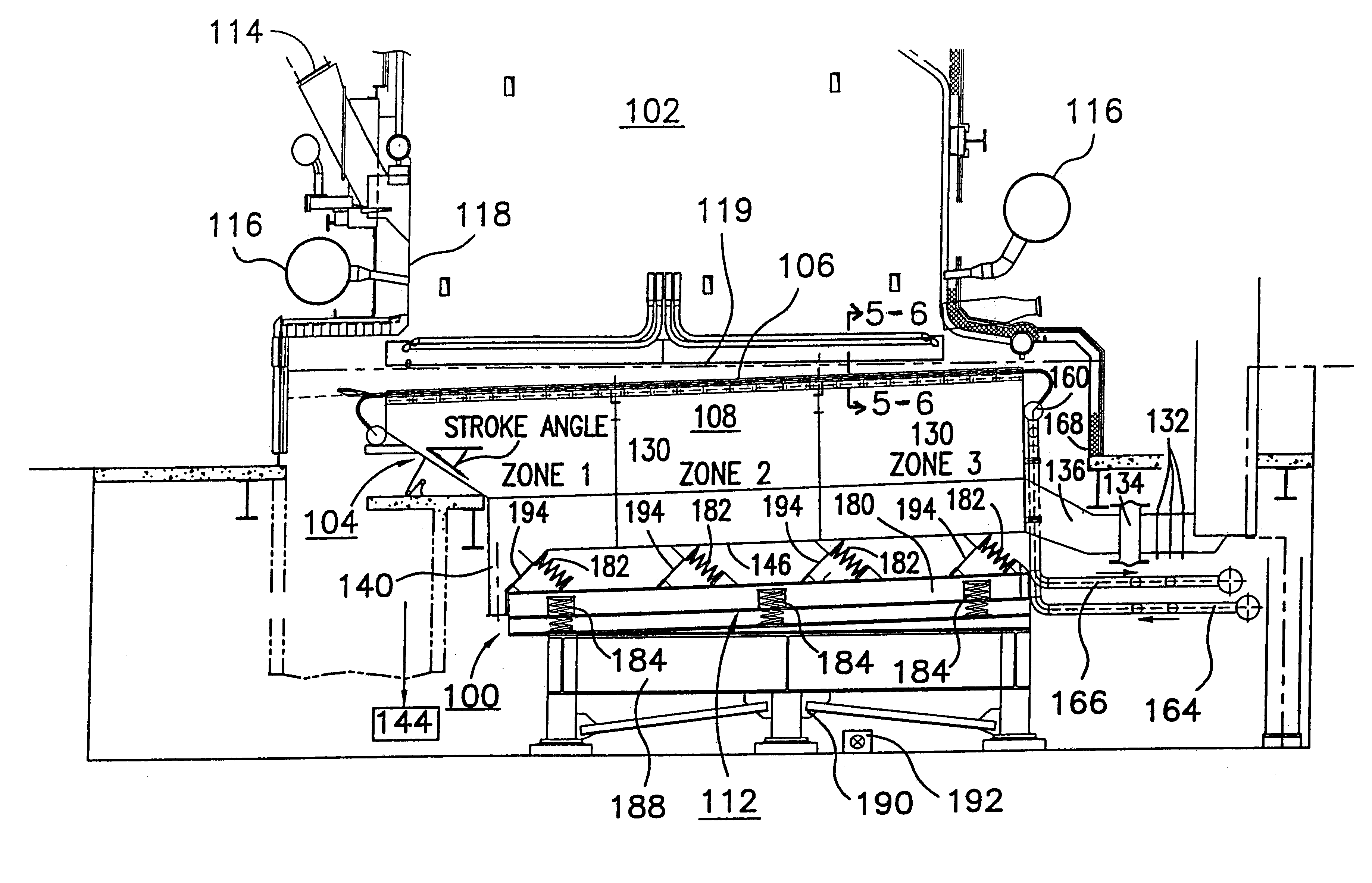
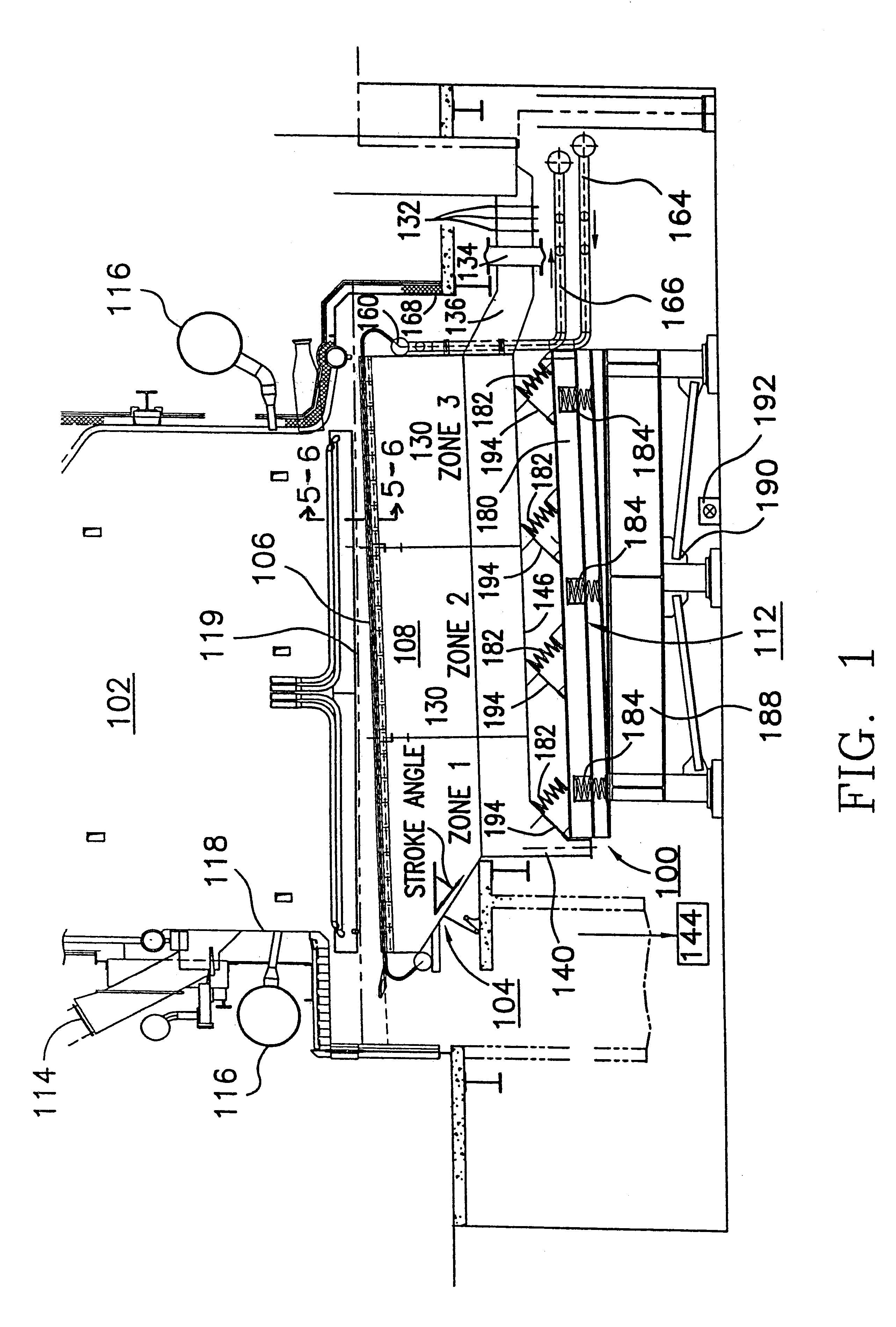
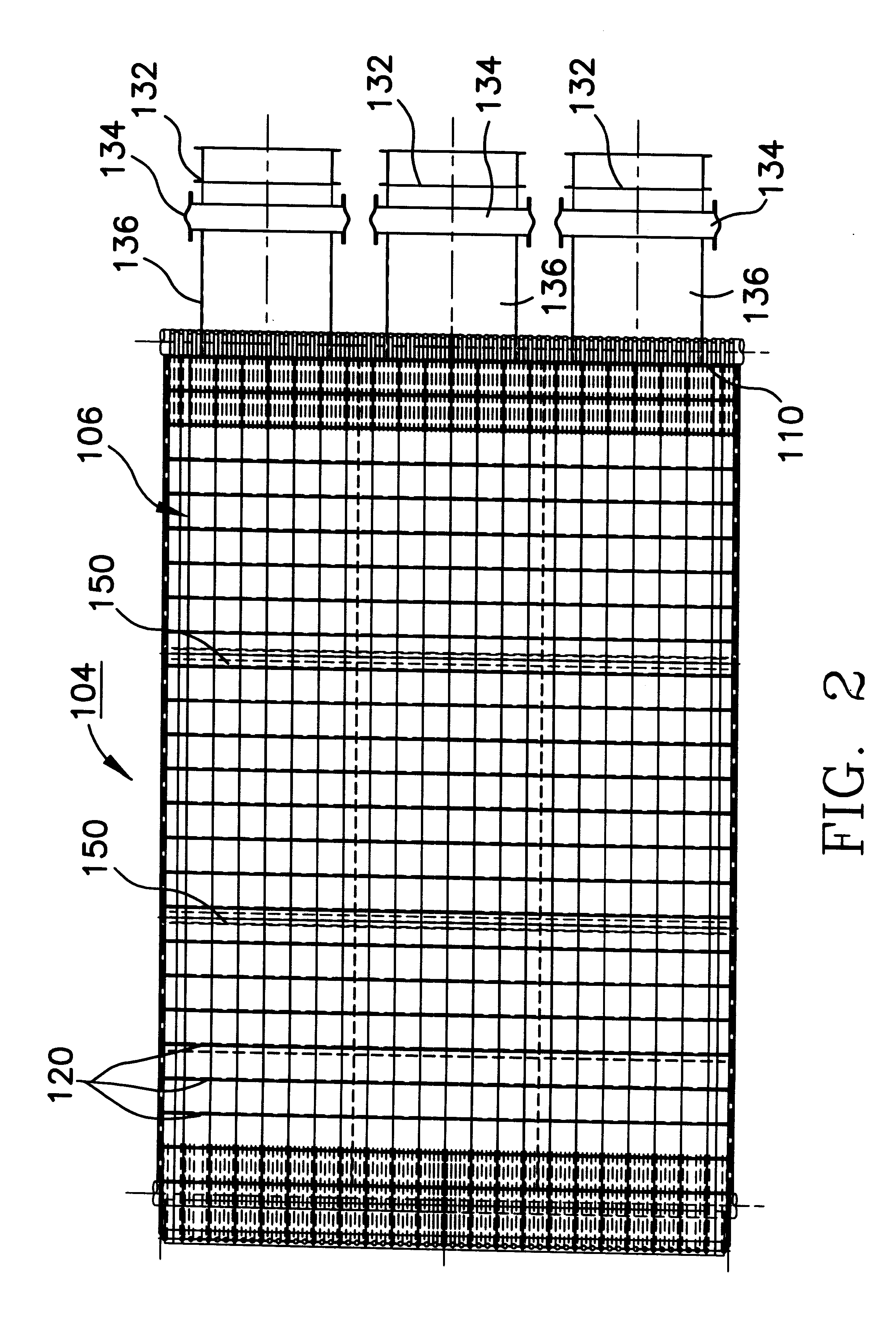
Having reference now to the drawing, FIG. 1 illustrates a water-cooled, air permeated, vibrating grate system generally designated by reference character 100 and arranged in accordance with the present invention in a boiler 102. In accordance with features of the invention water-cooled oscillating grate system 100 includes a single grate unit generally designated 104. Among its primary components, grate unit 104 includes a top grate surface 106, an air plenum 108 and a plurality of water cooling tubes 110. Grate unit 104 is an enclosed and air permeated, integral unit. Water-cooled, vibrating grate system 100 has a vibration isolated drive system generally designated by 112 arranged in accordance with the present invention. As shown in FIG. 1, the boiler 102 includes a fuel inlet 114 to permit fuel, such as biomass fuel, to be fed downwardly onto the grate surface 106. Boiler includes multiple overfire air ports 116 for supplying overfire air within the boiler shell 118. It should b...


PUM


Abstract

An integral water-cooled, air permeated, vibrating grate system for combusting biomass and other fuels in a boiler includes a grate top surface having air-flow apertures extending therethrough. The grate top surface is supported by a plurality of water-cooling pipes which arc coupled to a water supply. An enclosed air plenum unit is positioned under and attached directly to the grate top surface. The air plenum unit is coupled to an air supply for providing combustion air through the top grate surface air-flow apertures. The air plenum unit includes multiple zones, each of which zones has an associated air flow control damper so that the flow of combustion air can be controlled. Ash siftings formed on the grate top surface when the biomass or other fuel is combusted fall into the air plenum unit and flow toward at least one ash-siftings discharge opening at a discharge end of the air plenum when the grate top surface and the air plenum is vibrated. The grate top surface and the air plenum are vibrated together by a vibratory drive-isolation assembly which includes a longitudinally extending counterbalance member. A plurality of drive springs are supported by the counterbalance member. The drive springs are distributed across the width and the length of the top grate surface and at least one vibratory motor or mechanism is associated with the counterbalance member so that the vibration can be adjustably controlled.

Description

FIELD OF THE INVENTIONThe present invention generally relates to boiler systems, and more particularly, relates to a water-cooled oscillating grate system for a boiler, for example, used with biomass fuels.DESCRIPTION OF THE RELATED ARTVarious vibrating grate boiler arrangements are known. For example, U.S. Pat. No. 4,389,978 issued Jun. 28, 1983, discloses a grate having a fuel supporting and conveying surface including a plurality of elongate longitudinally-oriented, generally V-shaped channels. Water cooling pipes are provided for base and top part of each channel. Air feed openings are provided between both sidewalls of each channel. The grate is vibrated by a motor located outwardly of the boiler shell.U.S. Pat. No. 3,126,846 entitled INCINERATOR GRATE issued Mar. 31, 1964 discloses a grate including multiple, alternate stationary and movable grate members. The movable grate members are reciprocated relative to the stationary grate members from front to rear relative to the inc...

Claims


Application Information

Patent Timeline
IPC IPC(8): F23H7/00F23H3/00F23H17/00F23H17/08F23H3/02F23H7/18
CPCF23H3/02F23H7/18F23H17/08F23H2900/03021F23H2900/09041F23H7/04F23J1/06F23L1/02
Inventor DUMBAUGH, GEORGE DAVIDTOUPIN, KEVIN M.
Owner RILEY STOKER
Learn More