
Carbon dioxide cleaning and separation systems

a technology of carbon dioxide and cleaning and separation, applied in the field of cleaning and separation methods, can solve the problems of unsatisfactory efforts to replace such processes with aqueous systems, use environmentally undesirable solvents, energy consumption, etc., and achieve the effects of reducing drying times and problems with oxidation, and high cos

Inactive Publication Date: 2001-03-13
MICELL TECH INC
View PDF20 Cites 61 Cited by
  • Summary
  • Abstract
  • Description
  • Claims
  • Application Information

AI Technical Summary

Benefits of technology

An advantage of the invention is that the separation system is phase-tunable, in that the material of the second phase can alternately be rendered soluble, in whole or in part, or insoluble in the first phase, alternately rendering the material to be separated soluble or insoluble in the system in a controllable manner. Thus the system is a homogeneous system in one embodiment, when the second phase is wholly solubilized in the first phase to render the material to be separated insoluble therein.
is that the separation system is phase-tunable, in that the material of the second phase can alternately be rendered soluble, in whole or in part, or insoluble in the first phase, alternately rendering the material to be separated soluble or insoluble in the system in a controllable manner. Thus the system is a homogeneous system in one embodiment, when the second phase is wholly solubilized in the first phase to render the material to be separated insoluble therein.
The system is useful in a variety of applications, including cleaning, polymerization, extraction, coating, and particle formation and treatment. The system is particularly advantageous where the oil employed is of a relatively high cost. Since environmentally acceptable solvents such as organic or vegetable oils (including synthetic oils) can be relatively expensive, this system enables the use of such products in a broader variety of applications, in a cost-effective manner.
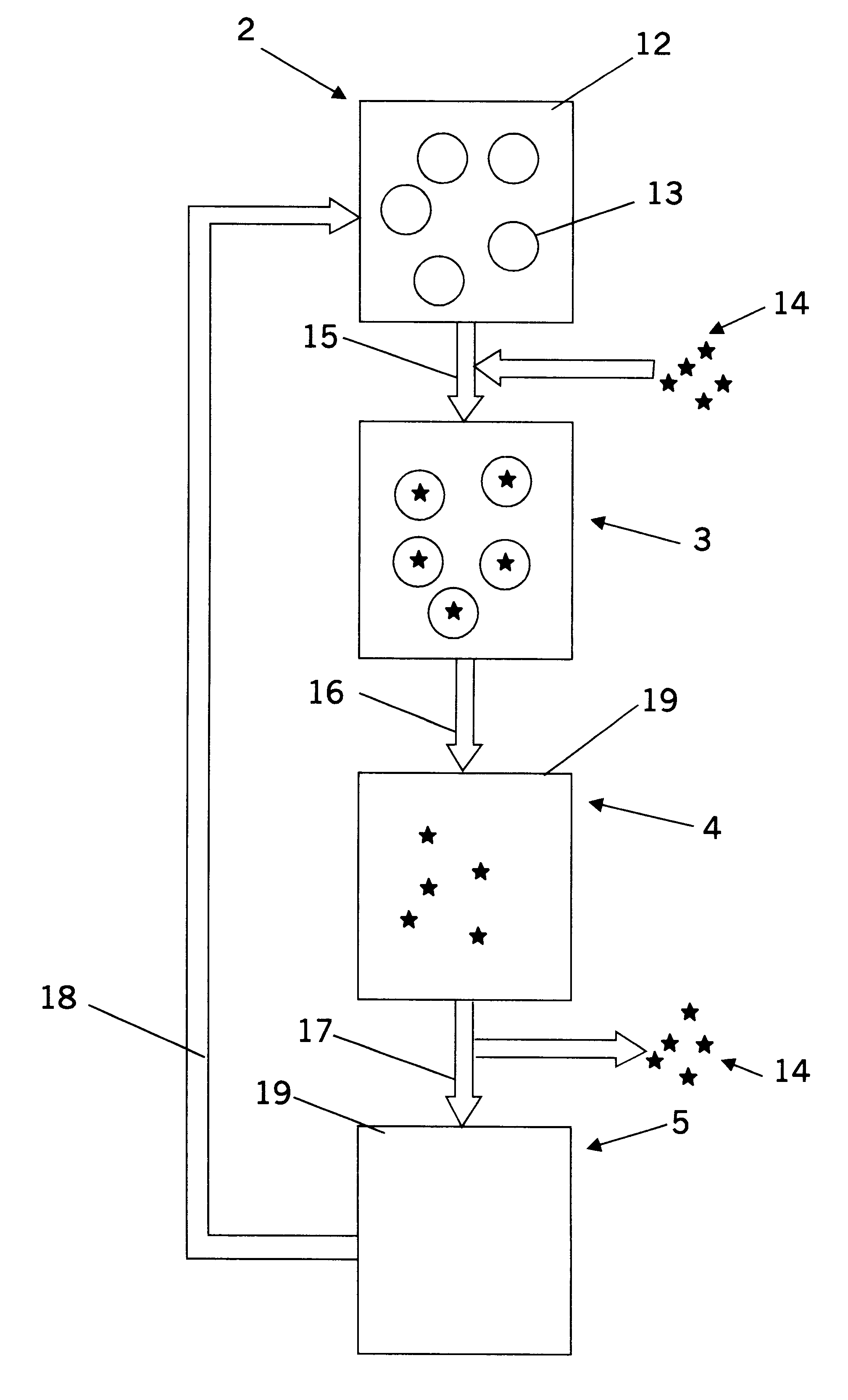
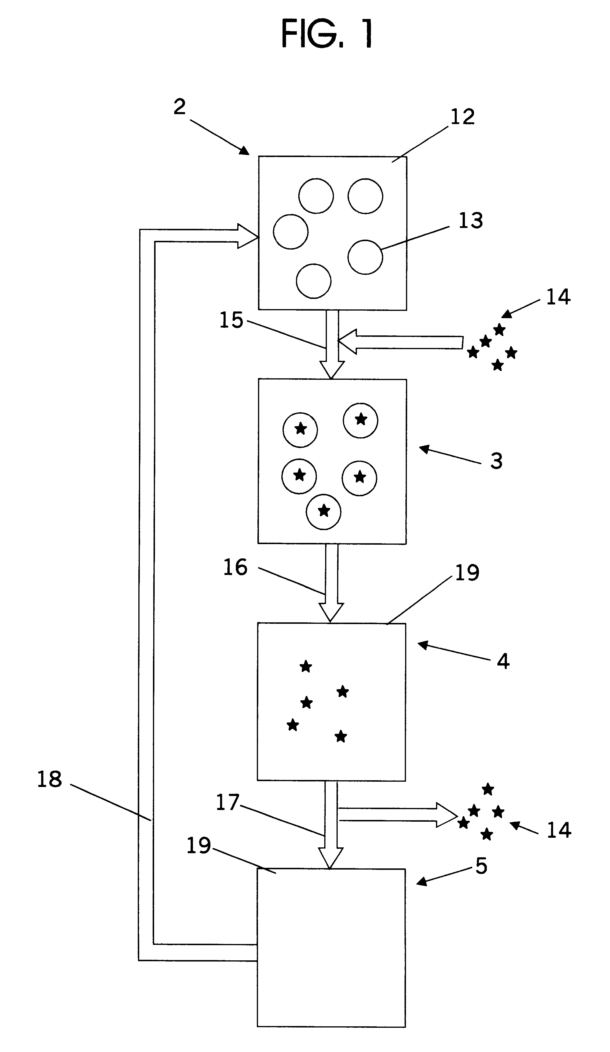
As noted above, one particular aspect of the invention is a method of cleaning a contaminant from a substrate. The method comprises contacting a substrate with a heterogeneous cleaning system. The heterogeneous cleaning system comprising CO.sub.2 in a first phase and a cleaner (preferably an oil such as an organic, or vegetable, oil) in a separate second phase, so that contaminant carried by said substrate is entrained in the cleaner. The cleaner is then wholly or partially solubilized in the first phase (e.g., by increasing the pressure of the system) to produce a cleaning system in which the contaminant is immiscible (e.g., a homogeneous cleaning system), and that contaminant is separated from the substrate. The substrate is separated from the cleaning system, either before or after the solubilizing step, and the contaminant (which has been rendered immiscible in the cleaning system) is separated from the cleaner. The cleaning system advantageously can be implemented as a non-aqueous system, thereby reducing drying times and problems with oxidation.
The foregoing and other objects and aspects of the present invention are explained in detail below.

Problems solved by technology

Unfortunately, many processes employ environmentally undesirable solvents, or are high temperature processes that are energy intensive.
Efforts to replace such processes with aqueous systems are not entirely satisfactory because of the problem of contacting water to substrates that may be oxidized thereby, and by the problem of cleaning the contaminated water.
In addition, the drying of aqueous systems is very energy intensive.
Vegetable oils such as soybean oil and modified soybean oil have been suggested for cleaning, but have not received significant use because of either their high cost or the difficulty in removing or extracting residual components of the oil.
Some employ supercritical CO.sub.2, which (due to the need to handle higher temperatures and / or pressures) increases the cost of the apparatus used to carry out the processes.
A problem with this system that it still does not provide a means to separate the contaminant from the co-solvent (see column 7, lines 24-32).

Method used


Image

  • Carbon dioxide cleaning and separation systems
  • Carbon dioxide cleaning and separation systems

Examples


example 1

Cleaning of a Screw Machine Part

Carbon steel machined nuts (200 g) coated with a heat quench oil (13 g) are added to a 1.6-L pressure-rated vessel at room temperature. SOYSOLV.RTM. (80 mL), an immiscible soybean oil obtained from Steyer Farms, Inc. (6154 N. Co. Rd. 33, Tiffin, Ohio, 44883 USA), is added and the vessel is filled with CO.sub.2 to liquid half full (.about.700mL at 850-875 psia). The parts are rotated at 5-10 RPM inside a mesh cage while the wash fluid is circulating and emulsified by a pump for 5 minutes. The wash fluid is then drained and the vessel is refilled with CO.sub.2 to 1000-1500 psia. The rinse liquid is circulated for 5 minutes and then drained. After the residual pressure is vented, the parts are removed from the vessel. No quench oil remains on the parts by visual inspection, and wiping the parts on a white sheet of paper leaves no residue.

In a separate chamber, the wash fluid is subjected to 1600 psig, solubilizing the SOYSOLV.RTM. oil in the CO.sub.2 pha...

example 2

Cleaning of Screw Machine Part

Carbon steel machined nuts (2.89 g) coated with a heat quench oil (0.01-0.05 g) are added to a 10-mL pressure-rated vessel at room temperature. An immiscible hydrocarbon solvent, 1.0 mL Isopar V, available from the Exxon Company, is added and the vessel is filled with CO.sub.2 to liquid half full (.about.5.0 mL at 850-875 psia). The wash fluid is stirred via a magnetically coupled stir bar for 5 minutes. The wash fluid is then drained and the vessel is refilled with CO.sub.2 to 1000-1500 psia. The rinse liquid is circulated for 5 minutes and then drained. After the residual pressure is vented, the parts are removed from the vessel. A major portion of the contaminant is removed from the parts as determined by visual inspection, and wiping the parts on a white sheet of paper leaves a slight residue.

In a separate chamber, the wash fluid is subjected to 1600 psig, solubilizing the SOYSOLV.RTM. in the CO.sub.2 phase and allowing separation of a substantial p...

example 3

Demonstration of "Oil" Solubilization Step

A 50:50 volume mixture of a heat quench oil and SOYSOLV.RTM. oil (8.5 g) is added to a 160-rnL pressure rated vessel at room temperature. Liquid CO.sub.2 (80 mL) at 850-875 psia is introduced into the vessel. The vessel contents separate into two liquid layers, and the bottom layer is drained from the vessel. This 4.70 g fraction is predominantly heat quench oil. The vessel is then depressurized by distillation of CO.sub.2. The remaining 3.63 g of oil is predominantly SOYSOLV.RTM. oil.


PUM

PropertyMeasurementUnit
Temperatureaaaaaaaaaa
pressuresaaaaaaaaaa
densitiesaaaaaaaaaa

Abstract

A separation method includes (a) providing a heterogeneous separation system, the heterogeneous cleaning system comprising CO2 in a first phase and an oil in a separate second phase; (b) entraining a material to be separated in the second phase; (c) wholly or partially solubilizing the second phase in the first phase to produce a separation system in which said material to be separated is insoluble; and then (d) separating the material from the system. The separating step is preferably followed by the step of (e) recovering at least a portion of the oil. The system is useful in a variety of applications, including cleaning (particularly metal cleaning), polymerization, extraction, coating, and particle formation and treatment.

Description

FIELD OF THE INVENTIONThis invention relates to cleaning and separation methods useful in cleaning substrates, particularly metal substrates, and useful for polymerization processes, coatings, extractions, and the manufacture and treatment of particles.BACKGROUND OF THE INVENTIONThe cleaning of contaminants from workpieces is an important step in many manufacturing processes. Unfortunately, many processes employ environmentally undesirable solvents, or are high temperature processes that are energy intensive. For example, vapor degreasing techniques employ both volatile organic solvents and high temperatures. Efforts to replace such processes with aqueous systems are not entirely satisfactory because of the problem of contacting water to substrates that may be oxidized thereby, and by the problem of cleaning the contaminated water. In addition, the drying of aqueous systems is very energy intensive.Vegetable oils such as soybean oil and modified soybean oil have been suggested for c...

Claims


Application Information

Patent Timeline
Patent Type & Authority Patents(United States)
IPC IPC(8): A61J3/06A61J1/00B01D12/00B01D11/04B05D1/18B08B3/10B08B7/04B08B7/00
CPCC11D7/44C11D7/50B08B7/0021
Inventor ROMACK, TIMOTHY J.MCCLAIN, JAMES B.STEWART, GINA M.GIVENS, RAMONE D.
Owner MICELL TECH INC
Learn More