Flexible vane coupling

Inactive Publication Date: 2001-03-13
DREW CHESTER
View PDF15 Cites 18 Cited by
  • Summary
  • Abstract
  • Description
  • Claims
  • Application Information

AI Technical Summary

Benefits of technology

Still another object and advantage of the invention is the simplicity in adding friction surfaces to increase torque output of the clutch.
is the simplicity in adding friction surfaces to increase torque output of the clutch.
Still another object and advantage of the present invention is to have smooth torque output as the friction elements slip against each other.
Additional objects and advantages include torque that can be different depending on whether the clutch is rotated in a clockwise or counterclockwise direction. Another additional object and advantage is the use of the device as a slip coupling where compliance between the two friction elements allows for concentric and angular misalignment between the two shafts that it connects.

Problems solved by technology

This creates a number of problems.
Using a large number of parts increases manufacturing cost and inherent inaccuracies due to tolerance stack-up.
Resulting problems can include inconsistent torque, backlash from poorly fitted parts; and with more parts, increased chances for failure.
Also, it is time consuming and costly in terms of labor to assemble a clutch with a variety of small pieces.
The present high cost of labor makes this type of clutch less desirable to produce now than in the past.
While a variety of inventions exist, many have involved complex designs that do not lend themselves to vary low-cost manufacturing and assembly procedures.
Such clutch designs do not produce torque unless the inner member is rotating.
As a result, this type of design is not made for slipping between members except for the brief period while engagement occurs.
As the friction surfaces wear however, the spring must wrap down further to maintain constant torque.
Torque output is very sensitive to wear due to the limited amount of radial movement of the wrap spring that is possible.
This creates a significant limitation to clutch life.
Furthermore, uneven radial forces result when the spring winds down onto the hub.
This causes uneven wearing of friction surfaces.
Additional manufacturing complexities and costs are required to overcome this problem.
This increases the complexity of the design.
With two concentric rings required to support friction surfaces, the chances for misalignment are greater.
Since torque is a function of force and distance from the center of rotation, reducing the diameter of the first friction surface reduces the torque it can produce.
This increases cost and complexity.
As described with wrap spring clutches, providing only one friction surface limits the maximum amount of torque which can be produced.
Increasing the number of friction surfaces beyond the one shown increases cost and complexity still further.
The low torque output limits commercial applications since many and users require relatively high torque.
As a result, torque is not smooth.
Second, torque is produced by cantilevered fingers extending axially from a plate.
Wear will be inconsistent since the part of the finger closest to the plate will not deflect as easily.
By the very nature of the design, the full length of the friction elements cannot be fully utilized.
As a result, clutch life and torque output will be reduced.

Method used


Image

  • Flexible vane coupling
  • Flexible vane coupling
  • Flexible vane coupling

Examples


Embodiment Construction

. 1-3

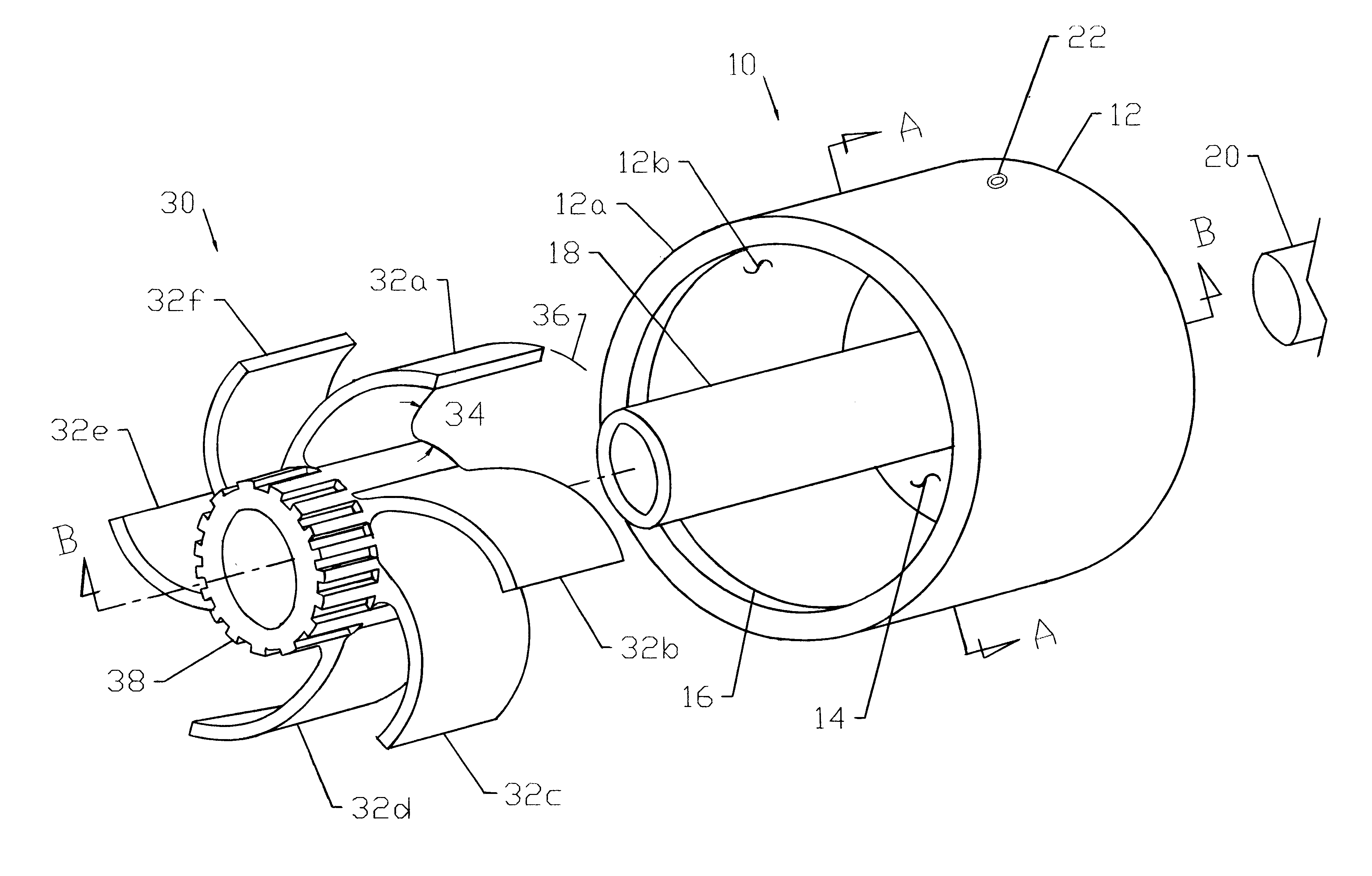
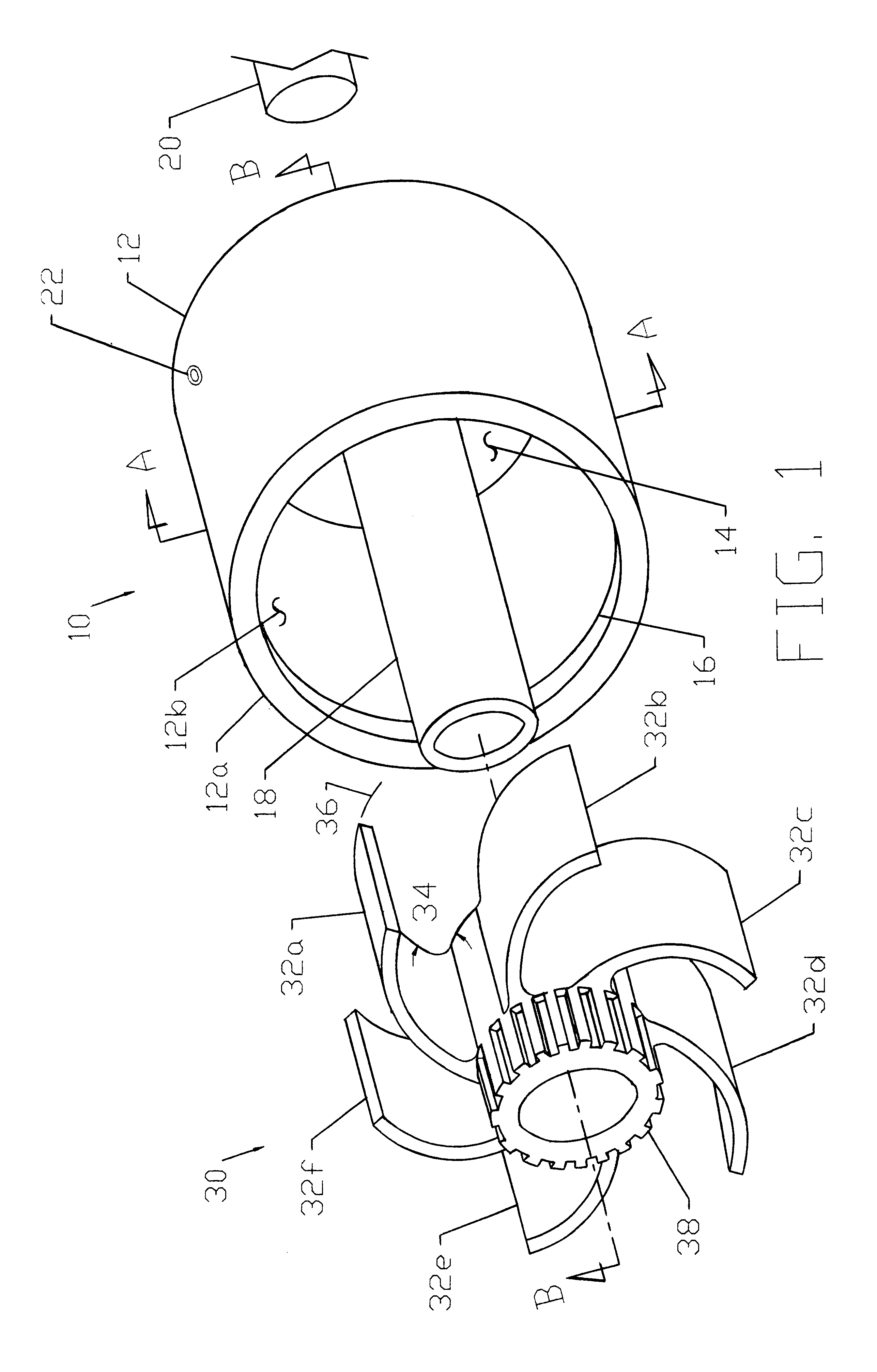
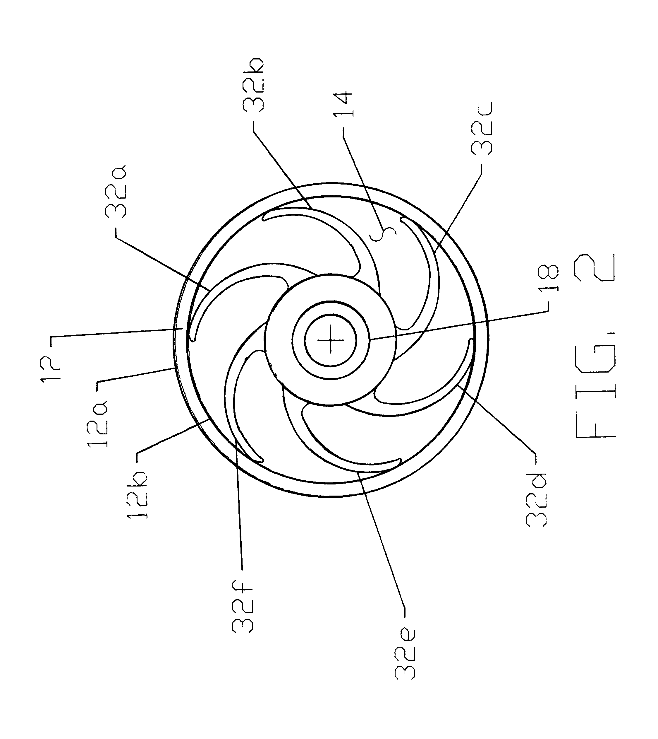
A perspective view of a typical embodiment of the clutch is shown in FIG. 1. The device comprises a housing and shaft assembly 10. The housing assembly 10 consists of a cylindrical shell 12 with an outer diameter 12a and an inner diameter 12b. Also comprised in the housing and shaft assembly 10 is a rear surface 14, a shoulder 16, and a shaft 18. The housing assembly 10 is preferentially made from die cast zinc. All surfaces have smooth "as cast" finishes. The shaft 18 is formed onto the rear surface 14 and extends beyond the cylindrical shell 12. The shaft 18 is hollow to allow for mounting the clutch to an external drive shaft 20. Attaching the housing assembly 10 to the drive shaft 20 can be accomplished with a set screw 22, interference press fit, keyway, or spline.

The shaft 18 could also be made from a separate piece of material and mounted into the rear surface 14 of the housing and shaft assembly. In this case, the material could be carbon steel for additional strength.

T...


PUM


Abstract

A slip coupling comprised of a hub with extending flexible vane(s). The vane(s) extend from the hub at an acute angle which allows them to flex when coming in contact with a relatively rotatable friction cylinder. The friction between the vane(s) and the friction cylinder creates resistance to movement. Relative motion between the hub and friction cylinder occurs only when the frictional force between them is overcome.

Description

This invention relates to a device which may be useful as a clutch or brake; more specifically, a slip friction clutch or brake with a minimal number of parts and long service life.BACKGROUND OF PRIOR ARTPrevious friction clutches consist of a multiplicity of small parts in order to achieve relatively high torque that is smooth in output. This creates a number of problems. Using a large number of parts increases manufacturing cost and inherent inaccuracies due to tolerance stack-up. The chances for parts not working together properly is also increased. Resulting problems can include inconsistent torque, backlash from poorly fitted parts; and with more parts, increased chances for failure. Also, it is time consuming and costly in terms of labor to assemble a clutch with a variety of small pieces. The present high cost of labor makes this type of clutch less desirable to produce now than in the past.While a variety of inventions exist, many have involved complex designs that do not le...

Claims


Application Information

Patent Timeline
IPC IPC(8): F16D7/00
CPCF16D7/002
Inventor DREW, CHESTER
Owner DREW CHESTER
Why Eureka
Try Eureka