Method of manufacturing progressive power spectacle lenses
a technology of progressive power and spectacle lenses, applied in the field of progressive power spectacle lenses, can solve the problem that the right and left clear view areas cannot be properly brought into coinciden
- Summary
- Abstract
- Description
- Claims
- Application Information
AI Technical Summary
Problems solved by technology
Method used
Image

Examples
first embodiment
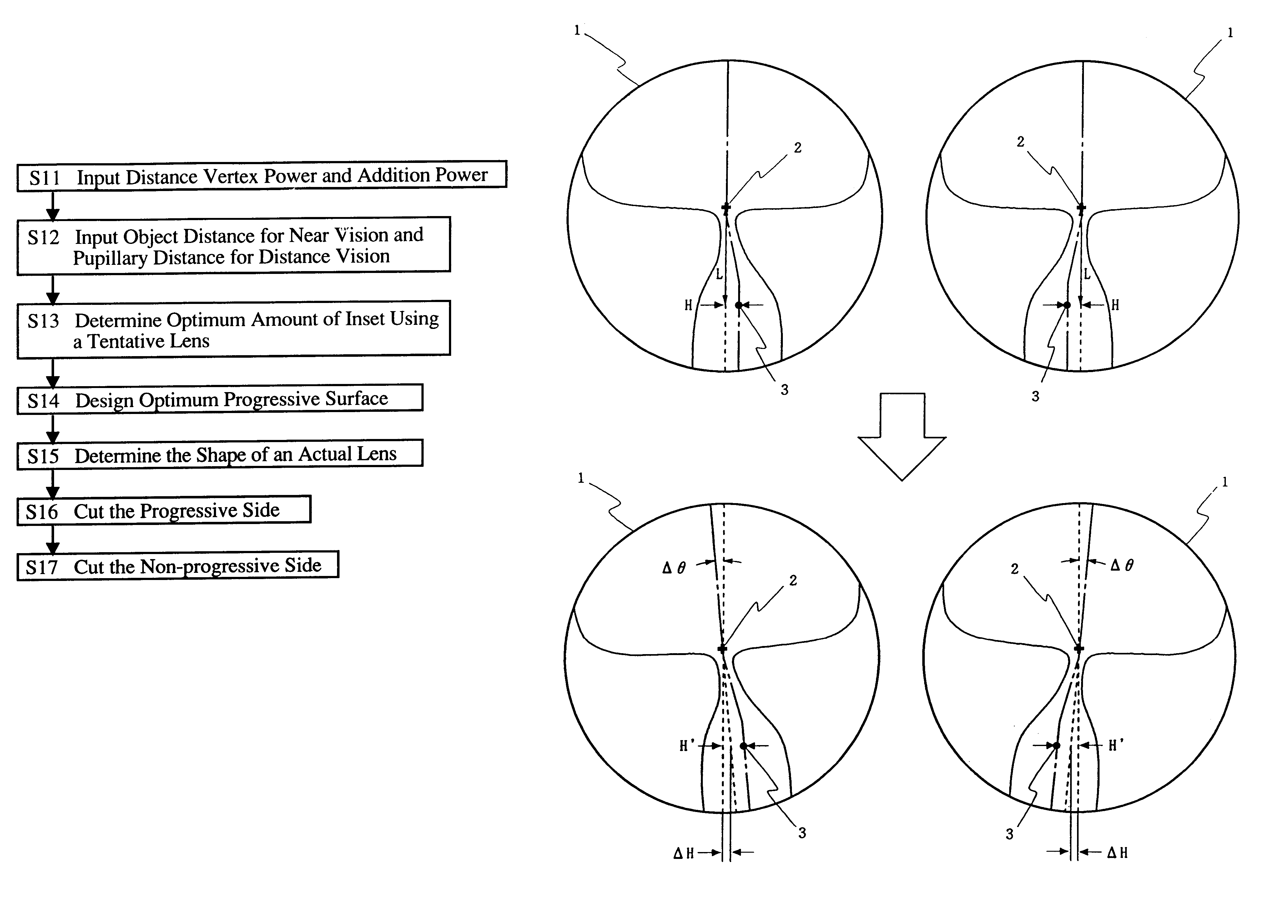
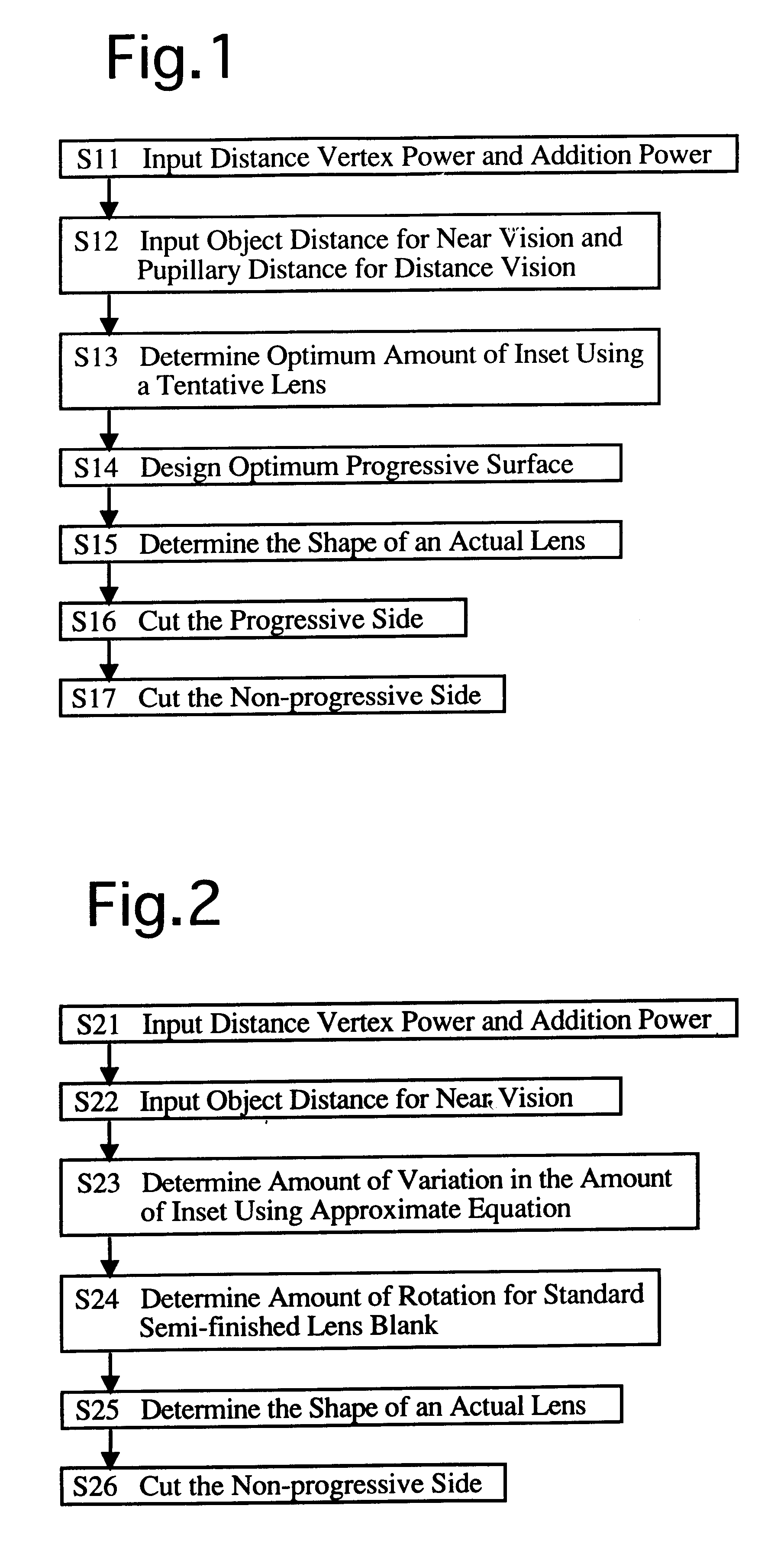
FIG. 1 shows a flow chart of a method of manufacturing progressive power spectacle lenses.
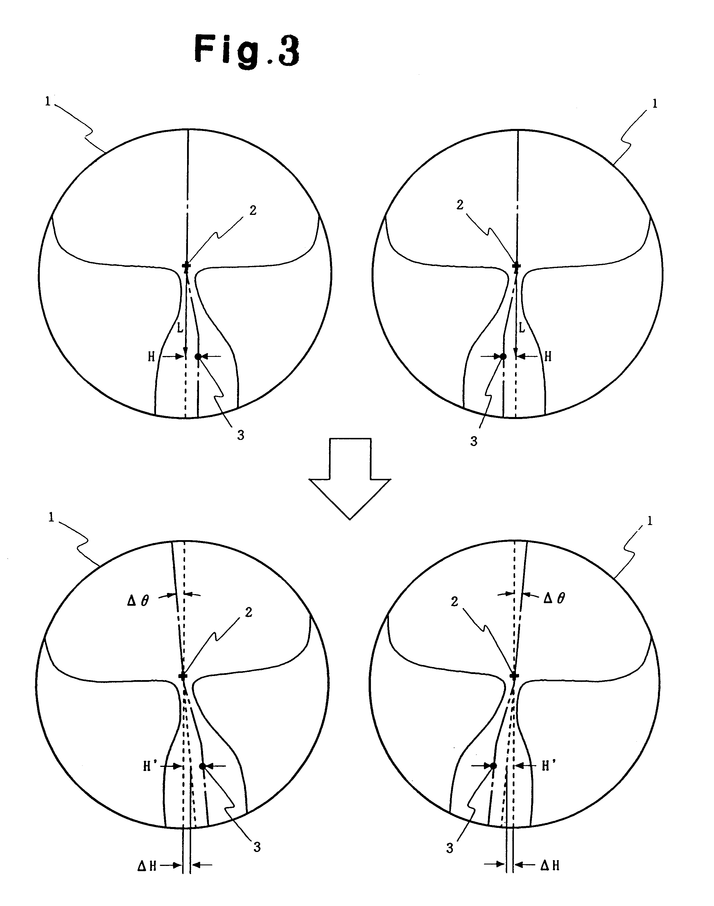
At step S11 the distance vertex power DF and the addition power ADD which are suitable to the vision of the lens-wearer are input into (for example) a computer which is connected to a high-precision 3-D NC milling machine for forming lens surfaces, via an input device such as a keyboard. If there is any designated data to be input such as prismatic power, such data is also input to the computer. At step S12 the object distance OD and the pupillary distance PD obtained from the pre-measured individual fitting condition data of the lens-wearer are input to the computer. In step S12 further data such as the distance EP from the point-of-rotation of the eyeball to the lens and the pantoscopic angle of the lenses when fitted onto the lens-wearer may be additionally input into the computer. All the aforementioned data at steps S11 and S12 can be sent from a retailer (spectacles retailer) to a manufac...
second embodiment
[SECOND EMBODIMENT]
FIG. 2 shows a flow chart of the second embodiment of a method of manufacturing progressive power spectacle lenses. In the second embodiment, a standard semi-finished lens blank is used so as to provide a progressive power spectacle lens having the optimum amount of inset at a low production cost. A "standard semi-finished lens blank" hereinafter refers to a progressive power semi-finished lens blank which is provided in advance on the progressive side thereof with a progressive surface which is designed with an assumed standard fitting state of the lens-wearer. Accordingly, the standard semi-finished lens blank is provided on the progressive side thereof with a progressive surface having an amount of inset according to a pre-determined standard.
The operation at step S21 is identical to the operation at step S11. The operation at step S22 corresponds to the operation at step S12; however, only the object distance OD is input to the computer in the operation at ste...
third embodiment
[THIRD EMBODIMENT]
FIG. 4 shows a flow chart of the third embodiment of a method of manufacturing progressive power spectacle lenses. In the third embodiment, similar to the second embodiment, the standard semi-finished lens blank is used so as to provide a progressive power spectacle lens having an optimum amount of inset at a low production cost.
The operations at steps S31 and S32 are identical to the operations at step S21 and S22. At step S33 the change in the amount of inset .DELTA.H is read out of a data table which is pre-calculated. FIG. 5 shows an example of such a data table. Column "A" of FIG. 5 is a list showing the relationship between the distance vertex power DF and the change in the amount of inset .DELTA.H, wherein only the object distance for near vision OD is changed while the pupillary distance between both eyes for distance vision PD and the distance EP from the point-of-rotation of the eyeball to the lens are set as constants (PD=65.00, EP=25.00). Likewise, the ...
PUM
 Abstract
Description
Claims
Application Information
 - R&D
- Intellectual Property
- Life Sciences
- Materials
- Tech Scout
- Unparalleled Data Quality
- Higher Quality Content
- 60% Fewer Hallucinations
Browse by: Latest US Patents, China's latest patents, Technical Efficacy Thesaurus, Application Domain, Technology Topic, Popular Technical Reports.
© 2025 PatSnap. All rights reserved.Legal|Privacy policy|Modern Slavery Act Transparency Statement|Sitemap|About US| Contact US: help@patsnap.com