
Method and apparatus for monitoring the breathing of a patient during magnetic resonance imaging

a magnetic resonance imaging and patient technology, applied in the direction of luminescent dosimeters, optical radiation measurement, instruments, etc., can solve the problems of patients' well-being, patient movement, and patients at risk of untoward complications

Inactive Publication Date: 2001-02-06
M2X
View PDF15 Cites 79 Cited by
  • Summary
  • Abstract
  • Description
  • Claims
  • Application Information

AI Technical Summary

Problems solved by technology

The patient's movements, which are commonly used as indicators of the patient's well-being, are extremely difficult to observe.
This creates concerns when imaging patients at risk of untoward complications while within the bore of the magnet.
First, a large percentage of patients develop mild to severe claustrophobia while within the confines of the magnet bore.
More sophisticated types of monitoring are not considered cost effective for these patients.
Second, more serious concerns arise when gadolinium contrast agents are administered, when agents for conscious sedation (such as benzodiazapines or synthetic opiates) are administered, or when patients are heavily sedated.
Third, patients that are medically unstable often require continuous monitoring of primary physiological parameters or they cannot be imaged at all.
Conventional patient monitoring equipment is unsuitable for use in or near an MRI system because: 1) it puts patients at risk for burns due to eddy currents generated within conductive parts, 2) conventional monitoring equipment frequently gives erroneous indications or malfunctions in the presence of the large static and changing magnetic fields, and radio frequency (RF) electric fields generated by an MRI system, and 3) conductive or magnetic parts can cause unacceptable distortion of the diagnostic images.
Both systems, however, make use of conductive parts, making the placement of sensors and associated cabling problematic.
In addition, these systems are expensive and complex, and as such are not commonly used outside of the most sophisticated imaging centers and hospitals.
At present, many patients who could benefit from MRI imaging are either put at risk for lack of any monitoring, or are ineligible for the procedure for lack of cost effective MRI compatible monitoring equipment.
Although these chest wall movement sensors are considered adequate for the reduction of motion artifact, they are not suitable for monitoring the patient's exchange of respiratory air.
In addition, patient movement unrelated the breathing will falsely trigger these type sensors.
Chest wall movement sensors are, therefore, not a reliable monitor of a patients well being.
The large magnetic and RF electric fields present in an MRI system, however, make these breath sensing methods unusable due to image distortion caused by induced magnetic fields of the temperature sensor and associated cabling, heating caused by induced currents in the temperature sensor and associated cabling, and noise induced in the temperature sensor and associated cabling by changing electromagnetic fields.
Indeed, any conductive or magnetic part placed in the bore of an MRI system is problematic because of the risk for patient burns, and the potential for image distortion compromising diagnostic quality.
Present commercial implementations of fiberoptic temperature sensors are not suited for breath sensing because: a) they often lack the required response time to follow breathing rates, especially those of hyperventilating patients, children, and neonates, b) they often lack the required sensitivity to resolve the small thermal variations in a patient's respiratory airstream, c) they are designed for very accurate measurement of temperature over a broad range and are thereby excessively costly, d) the sensor tips themselves are relatively expensive and thereby cannot be treated as a disposable item, which is often necessary in the medical environment to minimize the spread contagious disease, e) some devices employ conductive and / or magnetic materials in the sensor tip, mitigating their use in an MRI environment, and f) they lack a sufficiently long optical fiber to span the distance between the operator console and the MRI magnet bore.
Thus, none of these implementations anticipate their use for breath monitoring or breath monitoring during MRI imaging.

Method used


Image

  • Method and apparatus for monitoring the breathing of a patient during magnetic resonance imaging
  • Method and apparatus for monitoring the breathing of a patient during magnetic resonance imaging
  • Method and apparatus for monitoring the breathing of a patient during magnetic resonance imaging

Examples


Embodiment Construction

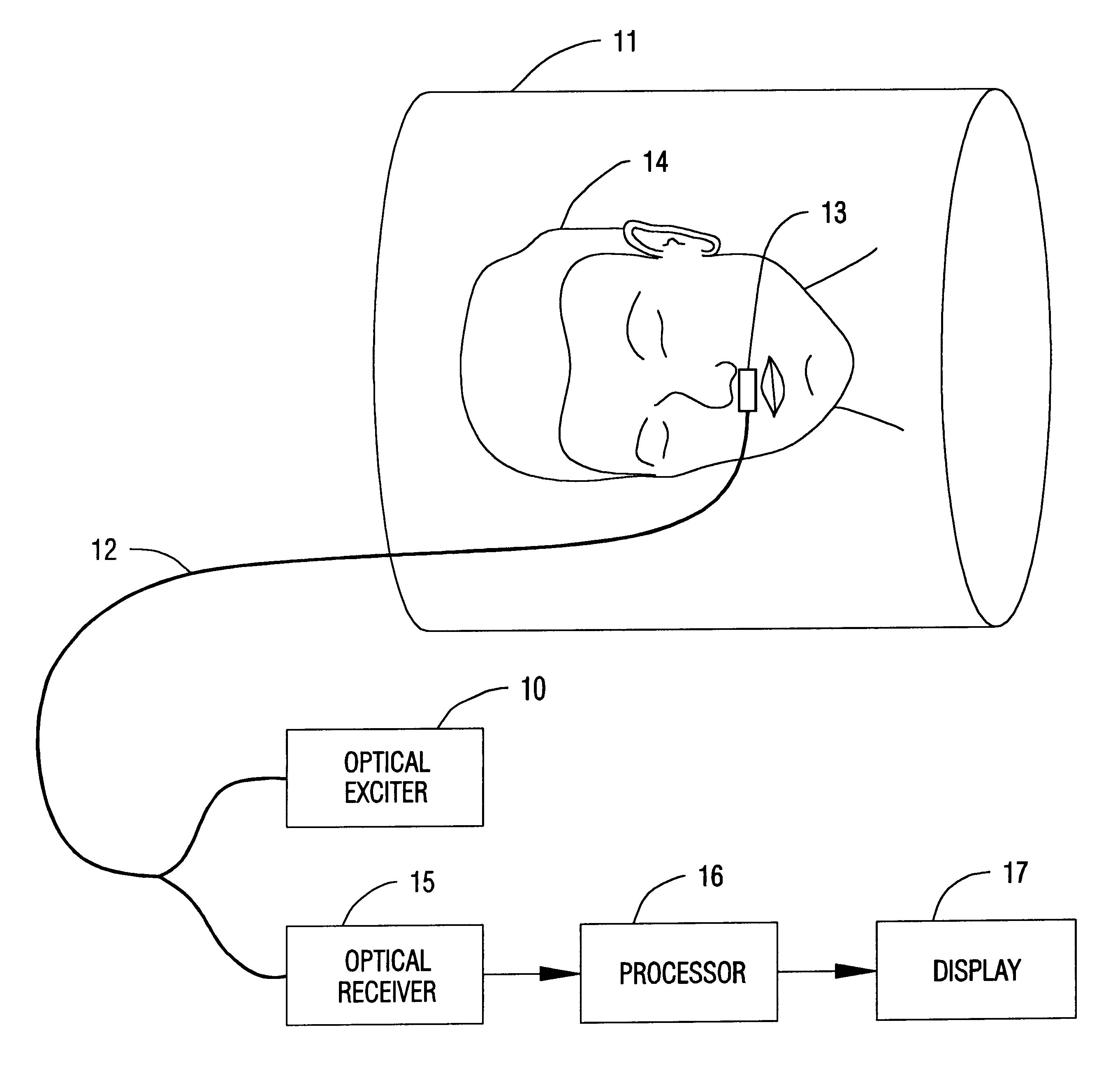
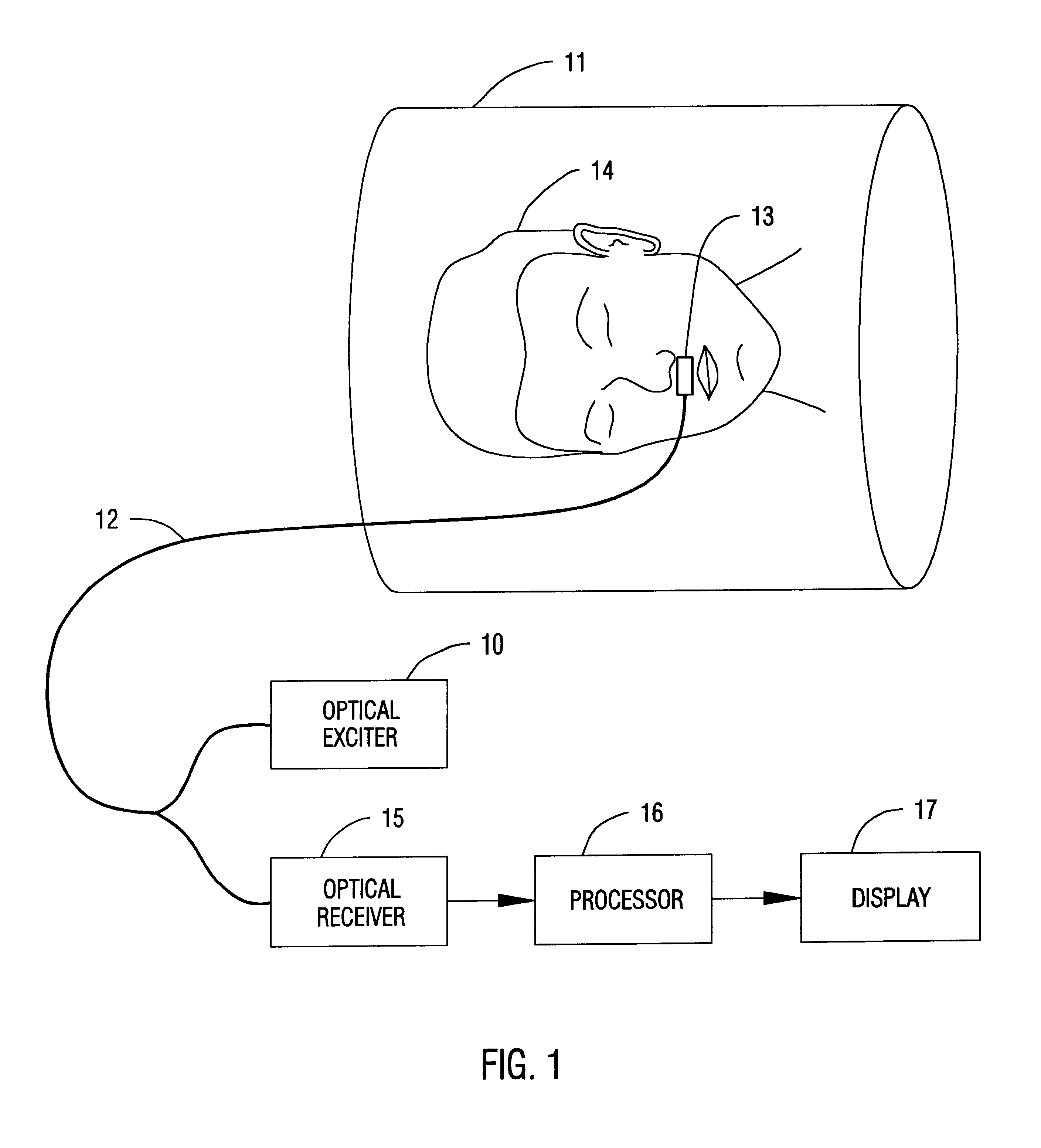
A generalized version of the present invention is illustrated in FIG. 1. An optical exciter 10 located away from an MRI magnet bore 11, sends an excitation light down an optical transmission means 12 consisting of one or more optical fibers, said optical transmission means going into MRI magnet bore 11, and thence to a temperature change sensing tip 13. A patient 14 is located inside MRI magnet bore 11. Temperature change sensing tip 13 is placed in the respiratory airstream of patient 14. Temperature change sensing tip 13 and those parts of optical transmission means 12 within MRI magnet bore 11 comprise materials which are substantially non-conductive and nonmagnetic. Blood pumped from patient 14's heart through the pulmonary artery and thence to the alveoli of the lungs, warms the air in the patient's lungs. As patient 14 breaths, thermal changes are induced in temperature change sensing tip 13 by the patient's expiration of warm air from his or her lungs, and by the patient's in...


PUM


Abstract

A breath sensor utilizes optical fibers to detect the flow of a patients respiratory airstream. As it has no conductive or magnetic parts, it can be used on patients within the bore of a magnetic resonance imaging system for simple, safe, and rapid assessment of a patient's breathing.

Description

1. Field of InventionThe present invention relates to a method and device for monitoring a patient's breathing during magnetic resonance imaging (MRI).2. Description of Prior ArtPatients undergoing an MRI exam are generally left isolated in a shielded room during the imaging procedure. When a patient is placed in the bore of the MRI magnet, he or she is nearly completely screened from view. The patient's movements, which are commonly used as indicators of the patient's well-being, are extremely difficult to observe. This creates concerns when imaging patients at risk of untoward complications while within the bore of the magnet.There are three classes of patients which warrant careful attention during MRI imaging. First, a large percentage of patients develop mild to severe claustrophobia while within the confines of the magnet bore. It is common practice to assess their status by speaking with them over an intercom system. More sophisticated types of monitoring are not considered c...

Claims


Application Information

Patent Timeline
Patent Type & Authority Patents(United States)
IPC IPC(8): A61B5/087A61B5/08A61B5/055
CPCA61B5/0873A61B5/055
Inventor CARLSEN, JR., WILLIAM F.
Owner M2X
Learn More