
Remote alert monitoring and trend analysis

a technology of remote alert monitoring and trend analysis, which is applied in the direction of digital transmission, data switching network, instruments, etc., can solve problems such as limitations to such support, data size transfer may be limited, and system performance degradation or system inoperativeness

Inactive Publication Date: 2001-01-30
ORACLE INT CORP
View PDF26 Cites 179 Cited by
  • Summary
  • Abstract
  • Description
  • Claims
  • Application Information

AI Technical Summary

Benefits of technology

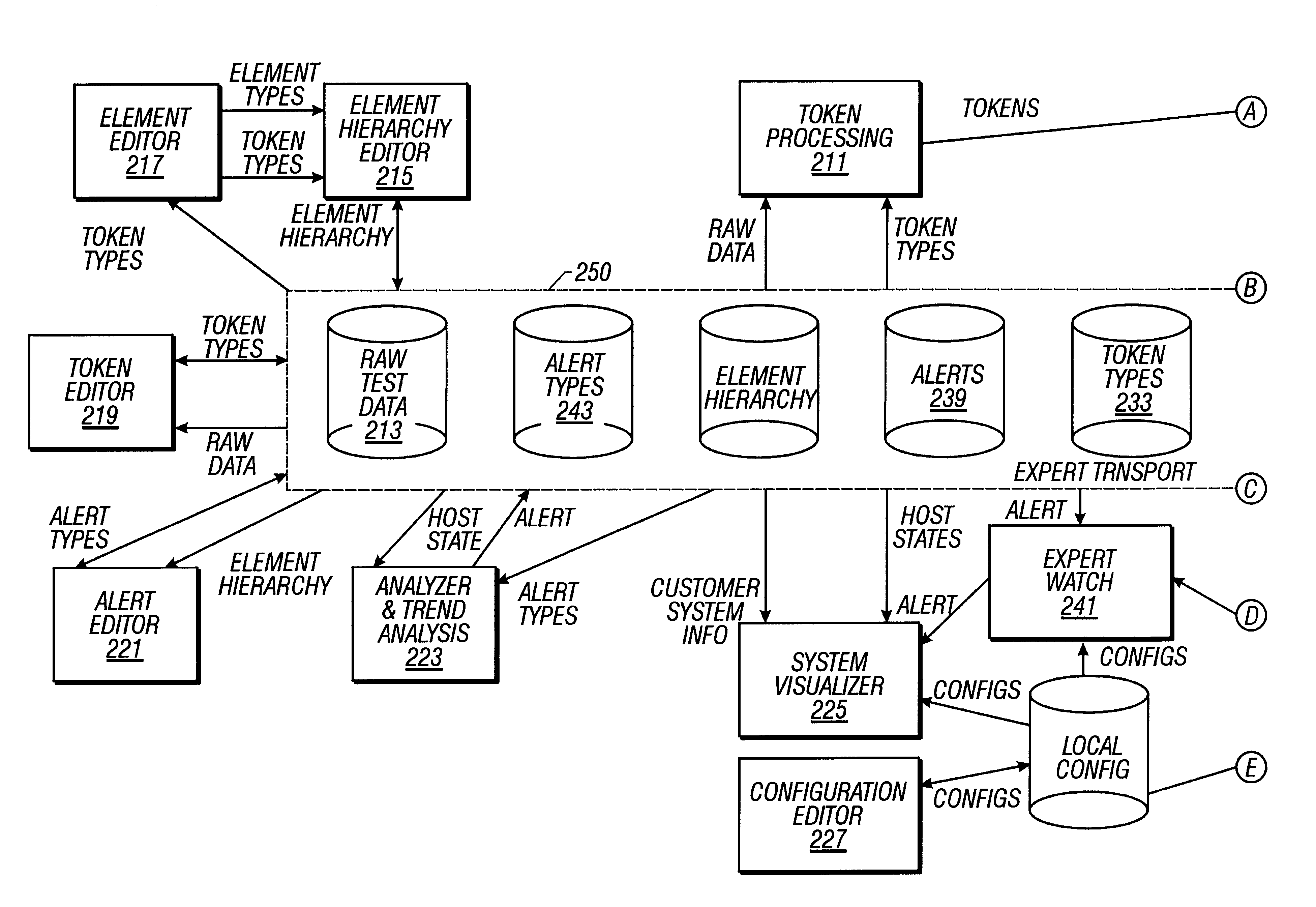
The method, apparatus and computer program products of the present invention provide a component based data structure for the diagnostic data that facilitates problem detection as well as proactive monitoring of the monitored computer system. Further, the present invention can build a representation of a monitored computer system without having any prior knowledge of the hardware and software details of the monitored computer system. Further, the invention can provide support for new computer systems and products in a manner that is more responsive than was previously available.

Problems solved by technology

Computer systems such as mainframes, minicomputers, workstations and personal computers, experience hardware and software failures that degrade system performance or render the system inoperative.
However, there are limitations to such support.
For instance, the data size transfer may be limited at the time of failure, due to such factors as modem speed and thus a complete picture of a system may be unavailable.
Running diagnostic software during the remote session, if necessary, may adversely impact system performance.
Where a system is part of a network, which is commonplace today, the running of diagnostic tests may impact network performance.
Where computer systems are being used in a production or other realtime environment, such degradation of system performance is obviously undesirable.
Further, historical data on system performance is not be available in such scenarios.
It is therefore impossible to analyze trends or compare system performance, e.g., before and after a new hardware of software change was made to the system.
The support engineer is limited to the snapshot of the system based on the diagnostic information available when the support engineer dials in to the system.
It would be advantageous if a support engineer had available complete diagnostic information rather than just a snapshot, However, system diagnostic tests typically generate a significant amount of data and it can be difficult for a support engineer to analyze such data in a raw form.
Each computer system has its own hardware and software components and thus have unique problems.
For example, it is not uncommon for failures to be caused by incorrect or incompatible configuration of the various hardware and / or software components of the particular system.

Method used


Image

  • Remote alert monitoring and trend analysis
  • Remote alert monitoring and trend analysis
  • Remote alert monitoring and trend analysis

Examples


Embodiment Construction

)

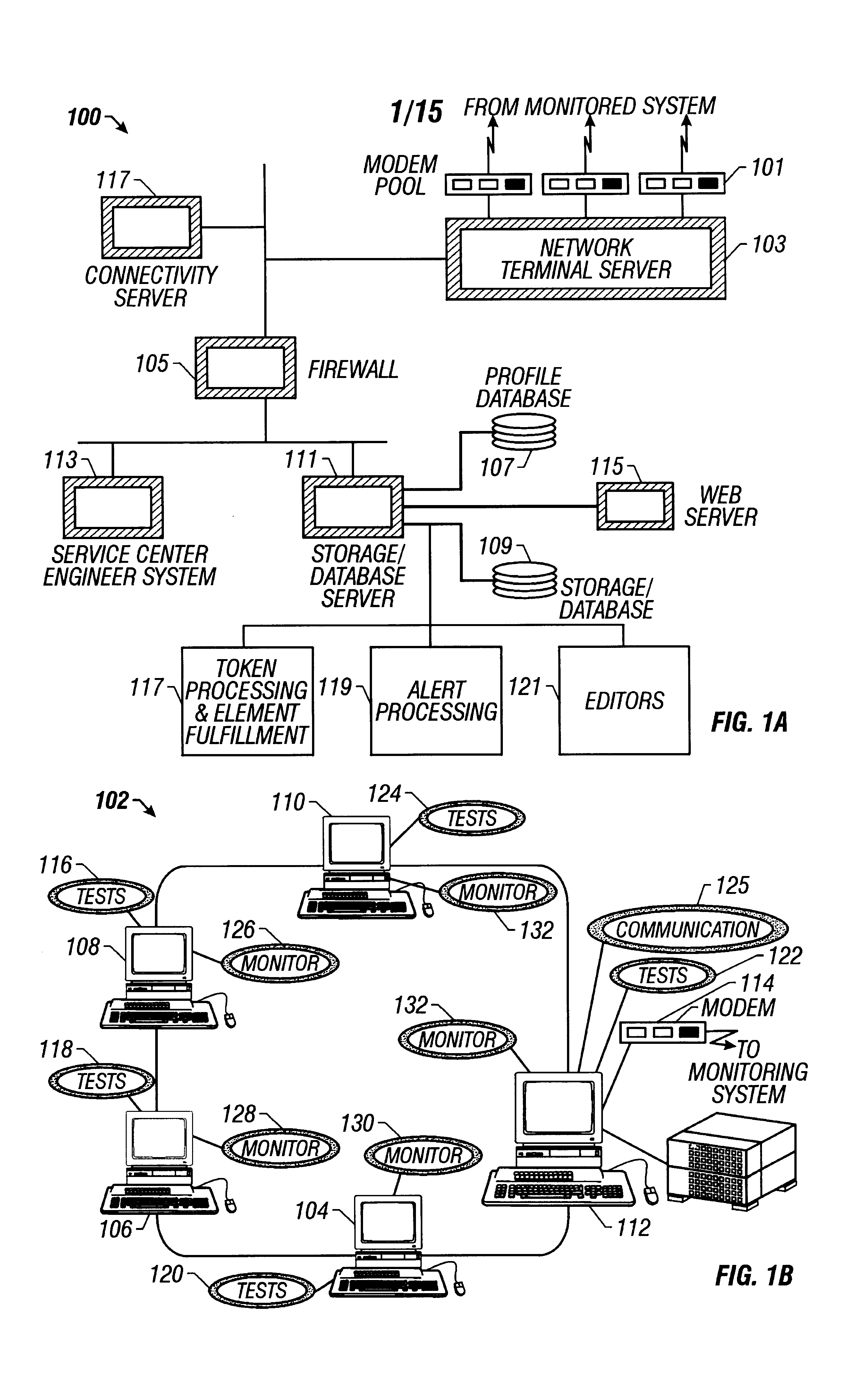
Referring to FIGS. 1a and 1b, an exemplary computer system 100, according to the present invention, receives diagnostic data from a monitored computer system 102. Monitored computer system 102 runs diagnostic tests, from among tests such as those shown in Table 1 or Table 2, on a periodic basis. The monitored system includes at least one computer and typically includes a plurality of computers 104, 106, 108, 110, and 112 coupled in a network as shown in FIG. 1b. The diagnostic tests 116, 118, 120, 122, and 124 are run on the computer system 102 under the control of monitor control software 126, 128, 130, 132, and 134. The results of those diagnostic tests are automatically provided at periodic intervals to the computer system 100 which monitors computer system 102. In exemplary computer system 100, which includes one or more computers and associated storage areas, preferably coupled in a network, incoming diagnostic data from monitored system 102 is received from modem 114 at one o...


PUM


Abstract

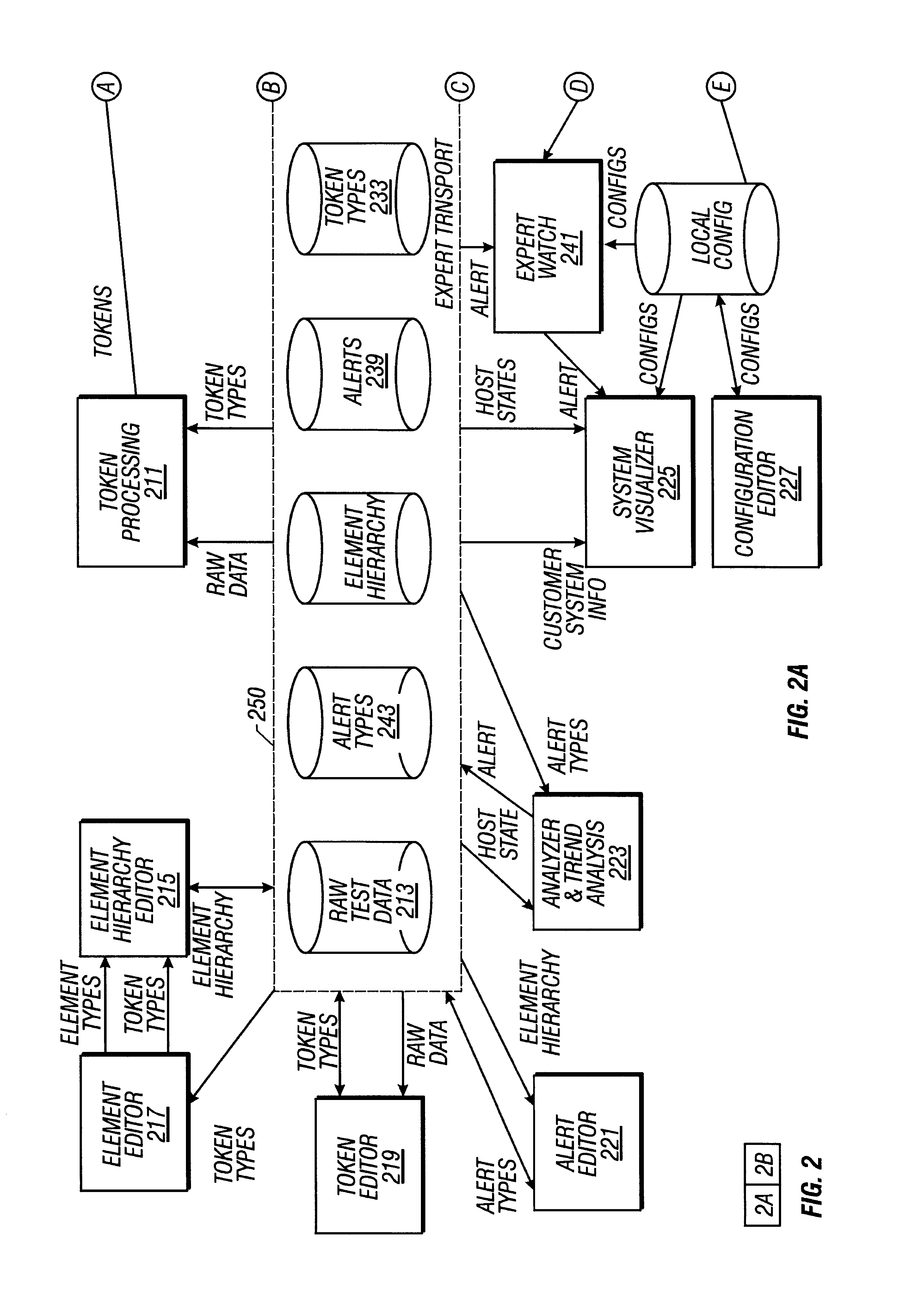
A monitoring system generates alerts indicating predefined conditions exist in a computer system. Alerts are generated by comparing alert definitions to a host state representing the state of the hardware and software components of a computer system. to determine if conditions defined in the alert definitions exist in the host state; and generating alerts accordingly. The host state is a static tree structure including elements in a fixed hierarchical relationship, the elements being given value by associated tokens, the elements and associated tokens representing the hardware and software components of the computer system. The alert definitions generate alerts according to the values of at least one token, at least one alert or a combination of various tokens and / or alerts. The host state is created by providing a static tree structure representing a general computer system. Component information indicating hardware and software components of the computer system is extracted from diagnostic data of the computer system. The host state is generated according to the static tree structure and the component information.

Description

1. Field of the InventionThis invention relates to monitoring of computer systems and more particularly to monitoring the state of a computer system.2. Description of the Related ArtComputer systems such as mainframes, minicomputers, workstations and personal computers, experience hardware and software failures that degrade system performance or render the system inoperative. In order to diagnose such failures computer systems include diagnostic capability which provides various types of system diagnostic information.Computer systems are typically serviced when a failure is noticed either by system diagnostics or by users of the system when the system become partially or completely inoperative. Since computer systems are frequently located at some distance from the support engineers, when problems do occur, a support engineer may access the computer system remotely through a modem in an interactive manner to evaluate the state of the computer system. That remote dial-in approach doe...

Claims


Application Information

Patent Timeline
Patent Type & Authority Patents(United States)
IPC IPC(8): G06F11/34H04L12/24H04L12/26
CPCG06F11/3461H04L12/2602H04L41/0681H04L41/22H04L43/00H04L43/045H04L43/0817H04L43/16
Inventor WOOKEY, MICHAEL J.CHU, KEVIN L.
Owner ORACLE INT CORP
Learn More