
Operative hinge for opening/closing body

a hinge and opening/closing technology, applied in the field of operative hinges, can solve the problems of difficult to elaborately fit the movement of the seat and lid, the seat and lid being opened or closed cannot be easily opened and closed, and the matching is not easy

Inactive Publication Date: 2001-01-30
KATOH ELECTRIC MACHINERY
View PDF8 Cites 41 Cited by
  • Summary
  • Abstract
  • Description
  • Claims
  • Application Information

AI Technical Summary

Benefits of technology

Accordingly, the present invention has an object to overcome the above-mentioned drawbacks of the prior art by providing an operative hinge of a simple structure destined for use with an opening / closing body such as a seat and seat lid of a toilet bowl and adapted to control the rotating moment of the opening / closing body to softly close the latter.

Problems solved by technology

Since it creates a rotating torque which will increase and decrease linearly, however, no easy matching is possible between the rotating torque and an angular moment of the seat and lid which will depict a sine curve, and it is difficult to elaborately fit the movement of the seat and lid as necessary to the rotating torque and also to appropriately control the movement of the seat and lid in each of the operating steps.
Further, the combination of a rotating shaft with only a rotating hydraulic damper is advantageous in that it is difficult to elaborately fit the moment of the seat and lid as necessary to the rotating torque and appropriately control the movement of the seat and lid in each of the operating steps, and that the seat and lid being opened or closed cannot easily be stopped and halted in au intermediate angular position and braked at a predetermined angular position the seat and lid have reached during each of the operating strokes, for example.

Method used


Image

  • Operative hinge for opening/closing body
  • Operative hinge for opening/closing body
  • Operative hinge for opening/closing body

Examples


Embodiment Construction

The present invention will be described hereinafter concerning an embodiment in which the operative hinge is used with a body adapted to be openable or closable such as a seat and seat lid of a toilet bowl. It should be noted, however, that the present invention is not limited to such au embodiment but it is applicable for various opening and closing structures

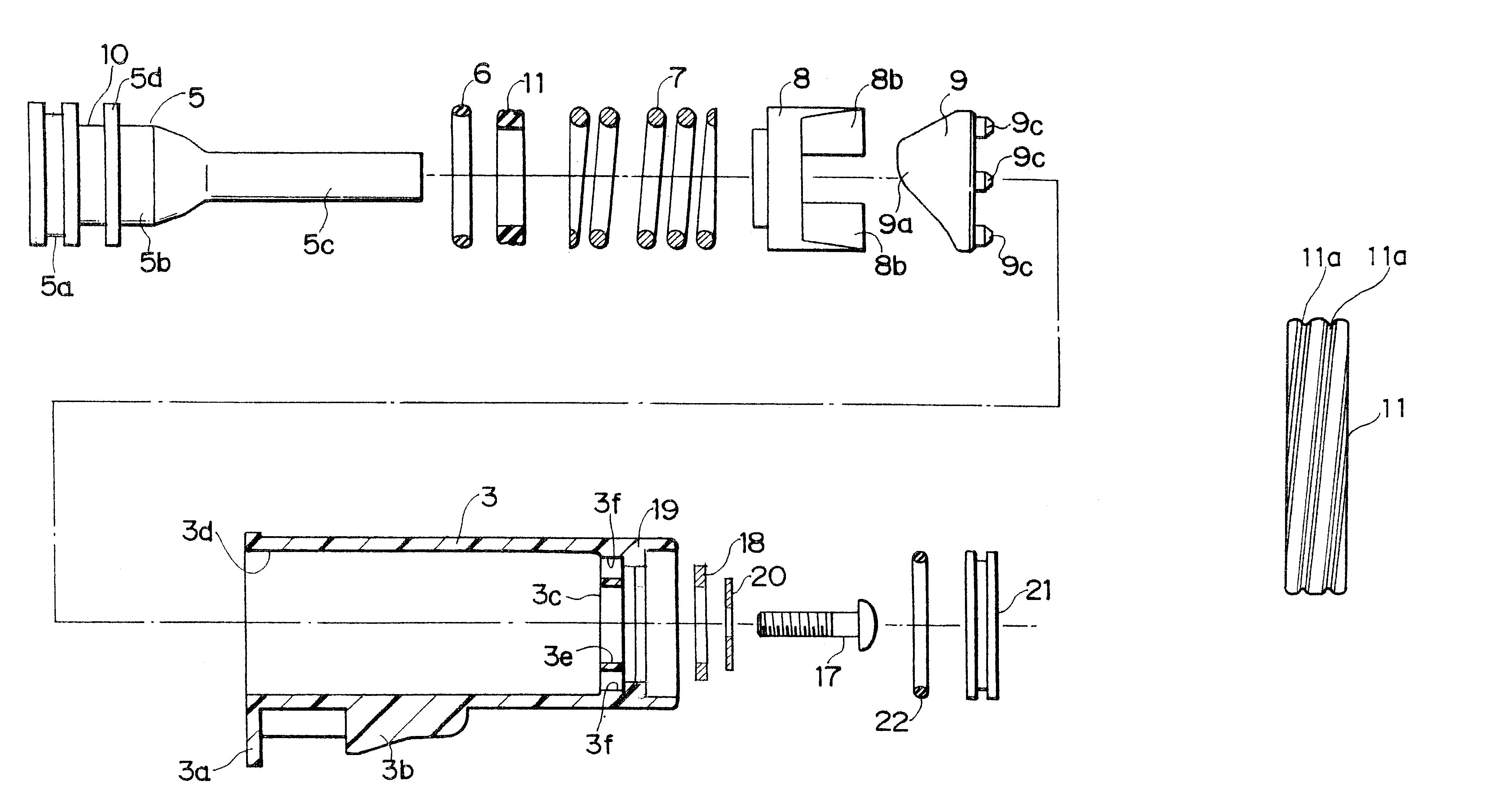
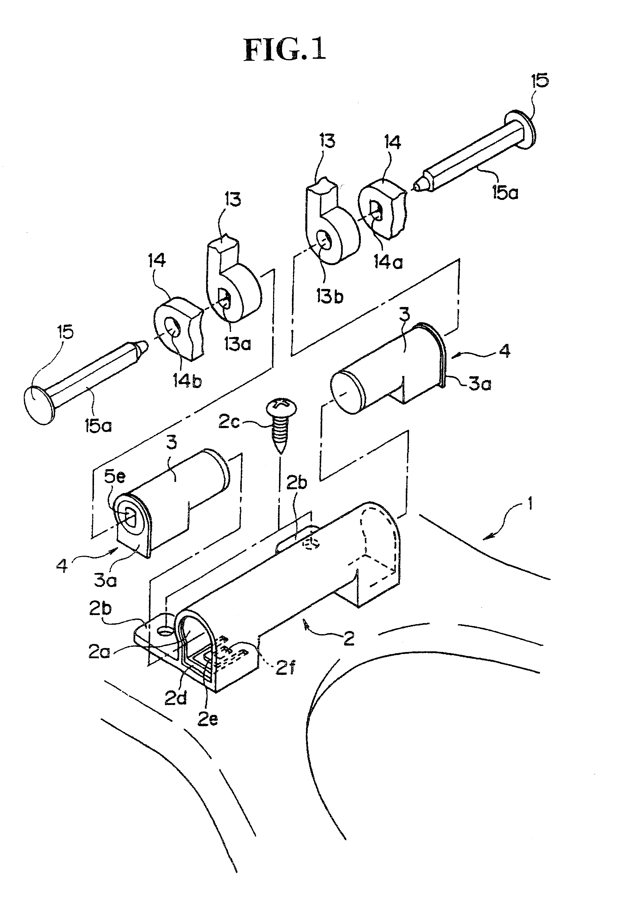
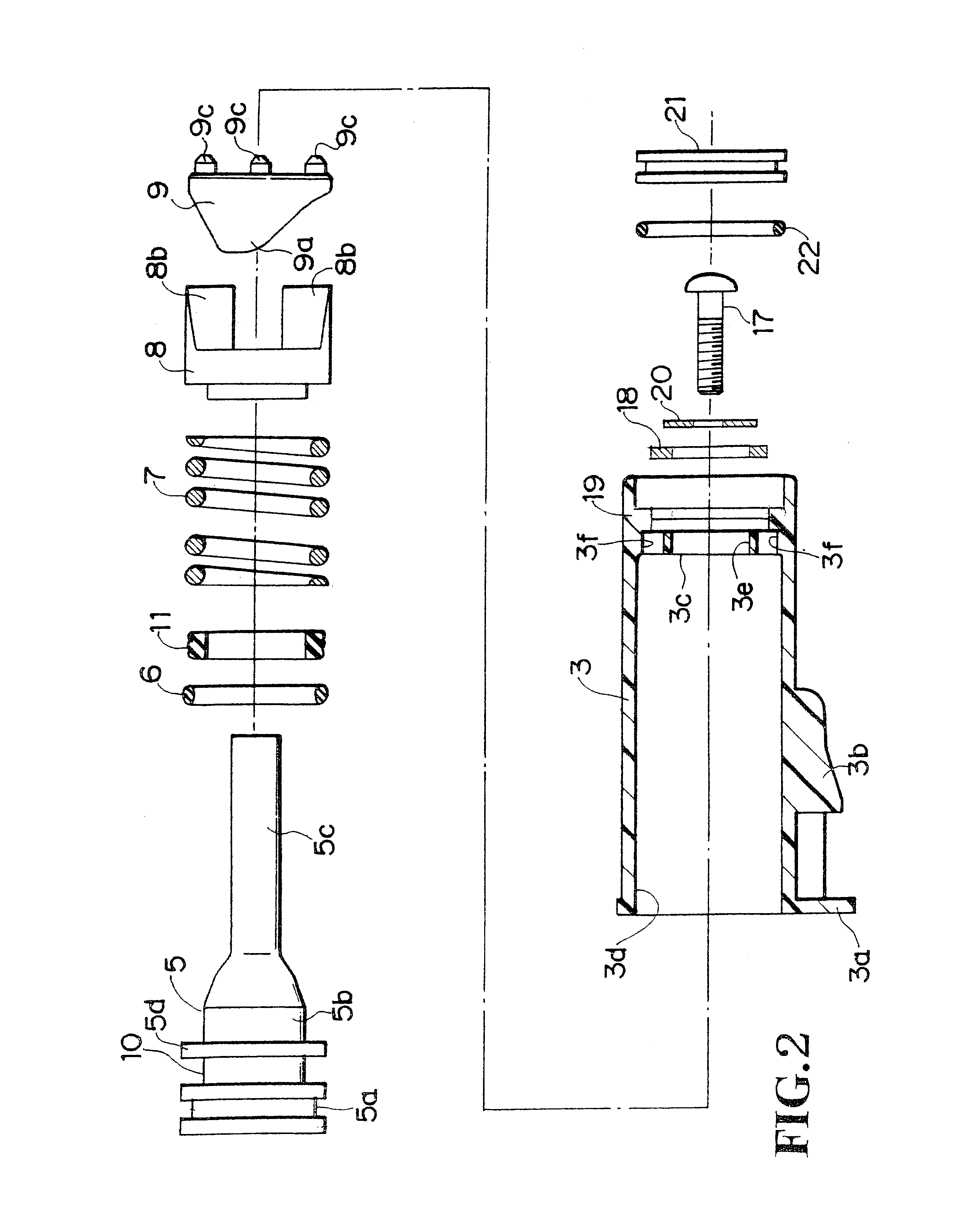
Referring now to FIG. 1, a toilet bowl is illustrated, by way of example, of which a body is generally indicated with a reference numeral 1. For installation of the operative hinge according to the present invention to the toilet bowl body 1, there is provided on, and nearly at the center of, the rear top of the toilet bowl body 1 a cylindrical fixture 2 open at either axial end thereof (namely, it has a pair of fixing bores of which only one 2a is illustrated herein) and having two rearward projecting plates 2b formed integrally with the cylinder 2. The cylinder 2 is to be secured to the body 1 of the toilet bowl with a pair ...


PUM


Abstract

An operative hinge for use with an opening / closing body is provided which comprises a hinge case to be installed to a toilet bowl body for operating the opening / closing body; a shaft provided rotatably within the hinge case to support the opening / closing body; a stationary cam fixed within the hinge case and having formed therein a central through-hole through which the rotating shaft is axially penetrated; a cam provided within the hinge case and having formed therein a central through-hole through which the rotating shaft is axially penetrated to be slidable on, and rotatable with, the rotating shaft; and a resilient means for urging the rotatable sliding cam toward the stationary can, the hinge further comprising, to further positively control the rotation or the rotating means, a damping means consisting of a rubber ring fitted on the rotating shaft and interposed between the outer surface of the rotating shaft and the inner wall of the hinge case; and a viscous oil applied between the outer surface of the rubber ring and inner wall of the hinge case; the rubber ring having spiral recesses formed on the outer surface thereof.

Description

BACKGROUND OF THE INVENTION1. Field of the InventionThe present invention relates to an operative hinge, and more particularly to an operative hinge suitable for use with an opening / closing body such as a seat and seat lid of a toilet bowl.2. Description of the Prior ArtVarious types of operative hinges for use with a seat and seat lid of a toilet bowl have been proposed so fax. Typical ones of such hinges include a combination of a shaft to support thereon the toilet seat and lid to be pivotable for opening or closing, with a cam mechanism incorporating a compression spring to act on the shaft, a combination of a rotating shaft and a torsion spring which acts to cancel a torque of the shaft being rotated in a predetermined direction, a combination of a rotating shaft and a rotating hydraulic damper, or a similar combinationThe combination of a rotating shaft with a cam mechanism incorporating a compression spring to act on the shaft is advantageous in that a matching can be easily ...

Claims


Application Information

Patent Timeline
IPC IPC(8): E05F1/00E05F1/12E05F3/14E05F3/00E05F3/20A47K13/12
CPCE05F1/1223E05F3/14E05F3/20E05Y2201/21E05Y2201/254Y10T16/2771E05Y2900/614Y10T16/54038Y10T16/540255Y10T16/5387E05Y2201/266E05Y2999/00
Inventor SUZUKI, NAOKAZUNAGASHIMA, ISAOSORIMACHI, AKIRAFUJITA, ORIYA
Owner KATOH ELECTRIC MACHINERY
Learn More