See-saw switch

a technology of seesaw switch and switch body, which is applied in the direction of snap-action arrangement, contact mechanism, electrical apparatus, etc., can solve the problem of unsatisfactory contact wearing

Inactive Publication Date: 2000-12-26
MATSUSHITA ELECTRIC WORKS LTD
View PDF1 Cites 7 Cited by
  • Summary
  • Abstract
  • Description
  • Claims
  • Application Information

AI Technical Summary

Problems solved by technology

Thus, the movable contact will first come into engagement with the fixed contact at almost zero initial contacting pressure which incurs an elongated contact bouncing time with an associated long arcing time, and therefore brings about undesired contact wearing.

Method used


Image

  • See-saw switch
  • See-saw switch
  • See-saw switch

Examples


Embodiment Construction

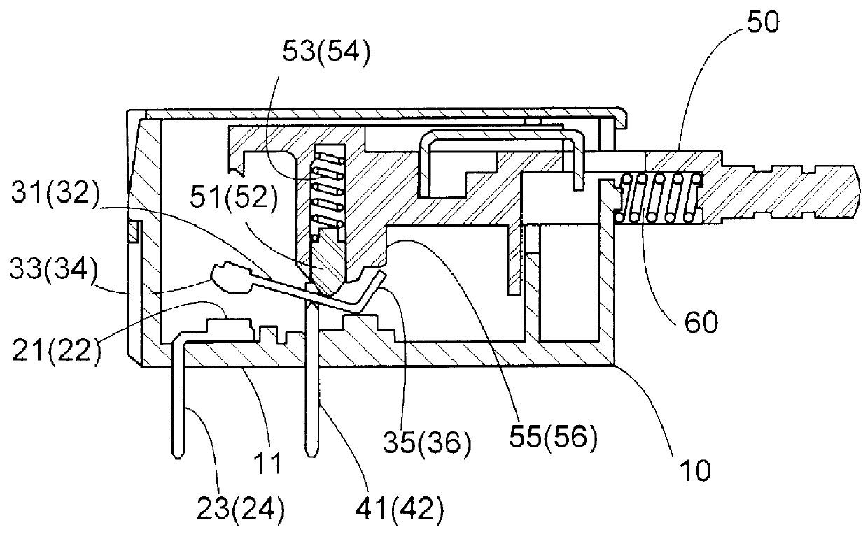
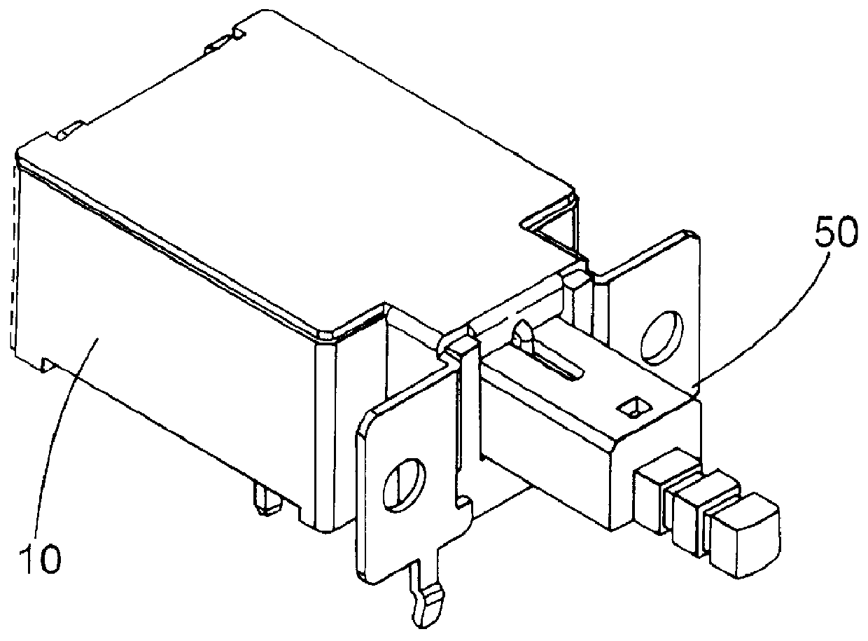
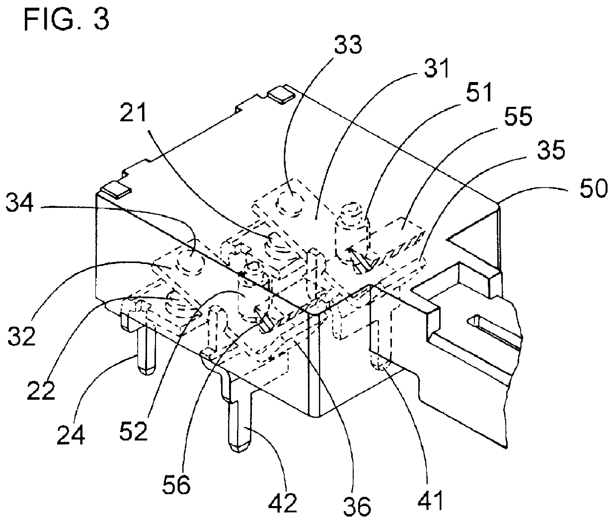
Referring to FIGS. 1 to 3, there is shown a see-saw switch in accordance with a preferred embodiment of the present invention. The switch is adapted in use as a latch-in type electrical power switch for a television set or the like electrical device, and is configured as a multi-pole switch having at least two contact sets for connection with an external circuit. The switch has a housing 10 which incorporates a pair of pivotable levers 31 and 32 each of which carries a movable contact 33, 34 at one lengthwise end of the lever for closing and opening to and from a complementary fixed contact 21, 22 mounted within the housing 10. The housing 10 includes a base 11 through which two pairs of terminal leads 41, 42 and 23, 24 project for electrical connection of the movable and fixed contacts respectively with the external circuit. The terminal leads 41 and 42 are each formed at its one end with a knife edge or a like pivot structure so as to pivotally support the lever 31, 32 for permitt...


PUM


Abstract

A see-saw switch capable of closing the contacts at a high initial contact pressure. The switch includes a housing provided with a fixed contact, and a lever provided with a movable contact at one longitudinal end thereof. The lever is pivotally supported to the housing for pivotal movement about a pivot axis between a contact closing position and a contact opening position. A plunger is slidably supported to the housing for linear movement along an axial direction of the plunger, and has an actuator which is held in slidable contact with said lever for translating the linear movement of the plunger into the pivotal movement of the lever so that, when the plunger moves in a forward direction, the actuator causes the lever to pivot about the pivot axis into the closed position. A restrictor is provided to keep the lever engaged with the plunger in order to restrict the lever from pivoting from the open position to the closed position until the actuator proceeds in the forward direction past a critical point which is offset from the pivot axis by a certain distance towards the movable contact along the lever. Thus, the lever operates to close the contacts only after the actuator past the critical point where it applies a sufficient force to the lever so as to impart the substantial initial contacting pressure between the contacts.

Description

1. Field of the InventionThe present invention is directed to a see-saw switch, and more particularly, an electrical toggle switch having a see-saw lever which is actuated by a plunger to pivot for contact closing and opening.2. Description of the Prior ArtJapanese Utility Model Laid-Open Publication No. 56-166623 discloses a known toggle see-saw switch. The see-saw switch includes a see-saw lever carrying a movable contact for closing with a complementary fixed contact mounted in a housing. The lever is pivotally supported to the housing and is actuated by a plunger to pivot about a pivot axis or fulcrum between a contact open position and a contact closing position. The plunger is slidably supported to the housing for linear movement along an axial direction of the plunger, and is formed at its one end with an actuator which is held in slidable contact with the lever for translating the linear movement of the plunger into the pivotal movement of the lever. This known switch is arr...

Claims


Application Information

Patent Timeline
Patent Type & Authority Patents(United States)
IPC IPC(8): H01H5/00H01H5/04H01H3/00
CPCH01H5/045H01H3/001
Inventor ITO, RYOJITAKEDOMI, YASUNARI
Owner MATSUSHITA ELECTRIC WORKS LTD
Why Eureka
Try Eureka