Filter for railroad car control valve pipe bracket and access plate

a technology for filtering and access plates, which is applied in the direction of filter cartridges, filtration separation, and separation processes, etc., can solve the problems of increasing the cost of manufacturers, suppliers and service facilities, and the hardware will not function properly

Inactive Publication Date: 2000-10-17
WESTINGHOUSE AIR BRAKE CO
View PDF11 Cites 15 Cited by
  • Summary
  • Abstract
  • Description
  • Claims
  • Application Information

AI Technical Summary

Benefits of technology

The technical effect of this patent is that it provides one interchangeable filter insert that can be used with both an SCTD Access Plate and a DPX Pipe Bracket without having to make separate filters for each component. This also eliminates the risk of installing the incorrect filter insert when trying to connect different parts together.

Problems solved by technology

The technical problem addressed in this patent text needs to be identified by a senior R&D personnel.

Method used


Image

  • Filter for railroad car control valve pipe bracket and access plate
  • Filter for railroad car control valve pipe bracket and access plate
  • Filter for railroad car control valve pipe bracket and access plate

Examples


Embodiment Construction

, particularly, when such description is taken in conjunction with the attached drawing figures as described below and with the appended claims.

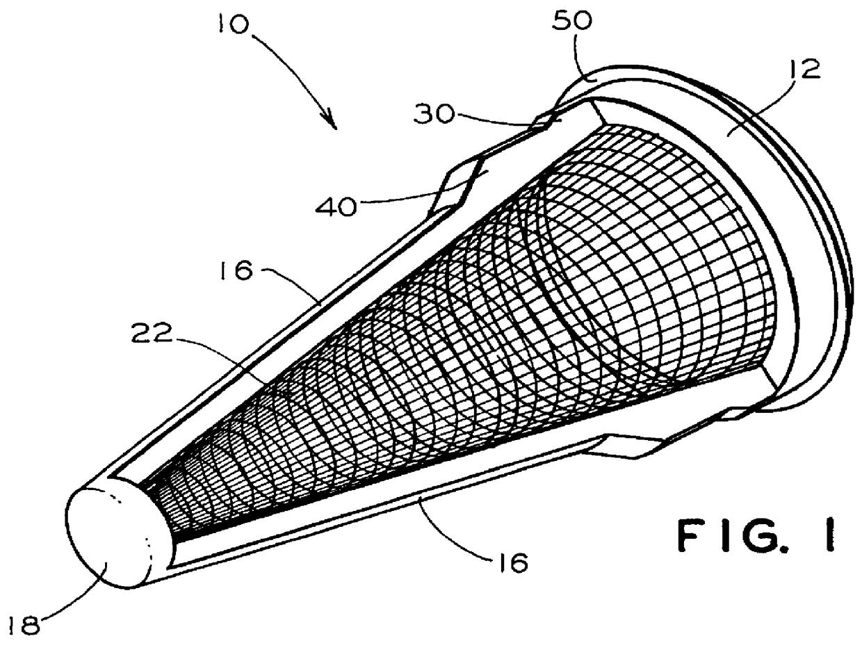
FIG. 1 is an isometric view of an insert filter in accordance with a currently preferred embodiment of this invention as designed to be press-fitted within either an SCTD Access Plate, or a DPX Pipe Bracket.

FIG. 2 is an enlarged side view of an upper portion of a support rib on the insert filter of FIG. 1 illustrating the primary and secondary flanges and the primary and secondary interface rib surfaces in detailed section.

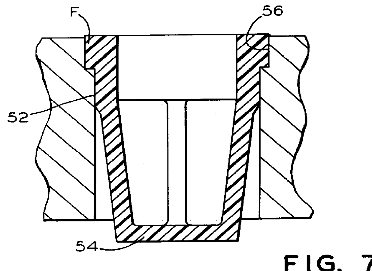
FIG. 3 is a cross-sectional view of the insert filter shown in FIGS. 1 and 2 as inserted into an airway port of a pipe bracket.

FIG. 4 is a cross-sectional view of the insert filter shown in FIGS. 1 and 2 as inserted into an airway port of an access plate.

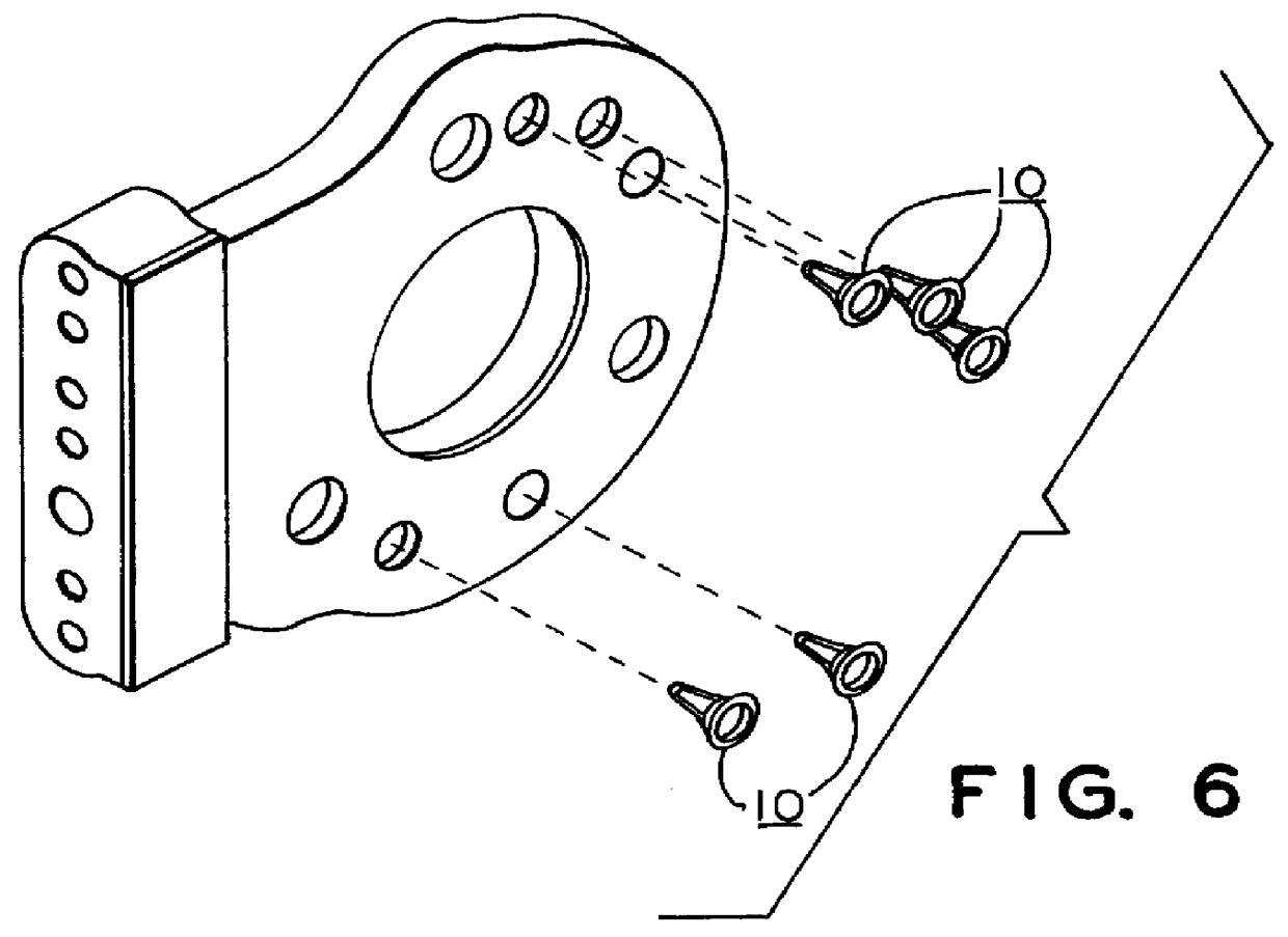
FIG. 5 is an isometric view of a pipe bracket showing where the insert filters of FIG. 1 are insertable.

FIG. 6 is an isometric view of an access plate showing where the in...


PUM

PropertyMeasurementUnit
Diameteraaaaaaaaaa
Volumeaaaaaaaaaa
Frictionaaaaaaaaaa

Abstract

An insert filter designed for press-fitting into airway port of hardware apparatus of a railway air brake system whereby the airway ports have at least two different diameters, the insert filter having a ring member defining an opening, a plurality of spaced support ribs extending from a first side of the ring member and intersecting at a location spaced from that first side of the ring member, and a screen mesh supported by the plurality of spaced rib supports defining a volume adjacent to the opening through the ring member. Each of said support ribs having a primary interface rib surface adjacent to an outer edge surface of the ring member adapted to engage inner edge surfaces of a larger, first airway port, and a secondary interface rib surface adjacent to the primary interface rib surface adapted to engage inner edge surfaces of a smaller second airway port.

Description


Claims


Application Information

Patent Timeline
Owner WESTINGHOUSE AIR BRAKE CO
Why Eureka
Try Eureka