Atomizing pump spray

Inactive Publication Date: 2000-10-03
OLEGNOWICZ ISRAEL
View PDF11 Cites 23 Cited by
  • Summary
  • Abstract
  • Description
  • Claims
  • Application Information

AI Technical Summary

Problems solved by technology

The drawback with the separate control is the greater number of

Method used


Image

  • Atomizing pump spray
  • Atomizing pump spray
  • Atomizing pump spray

Examples


Example

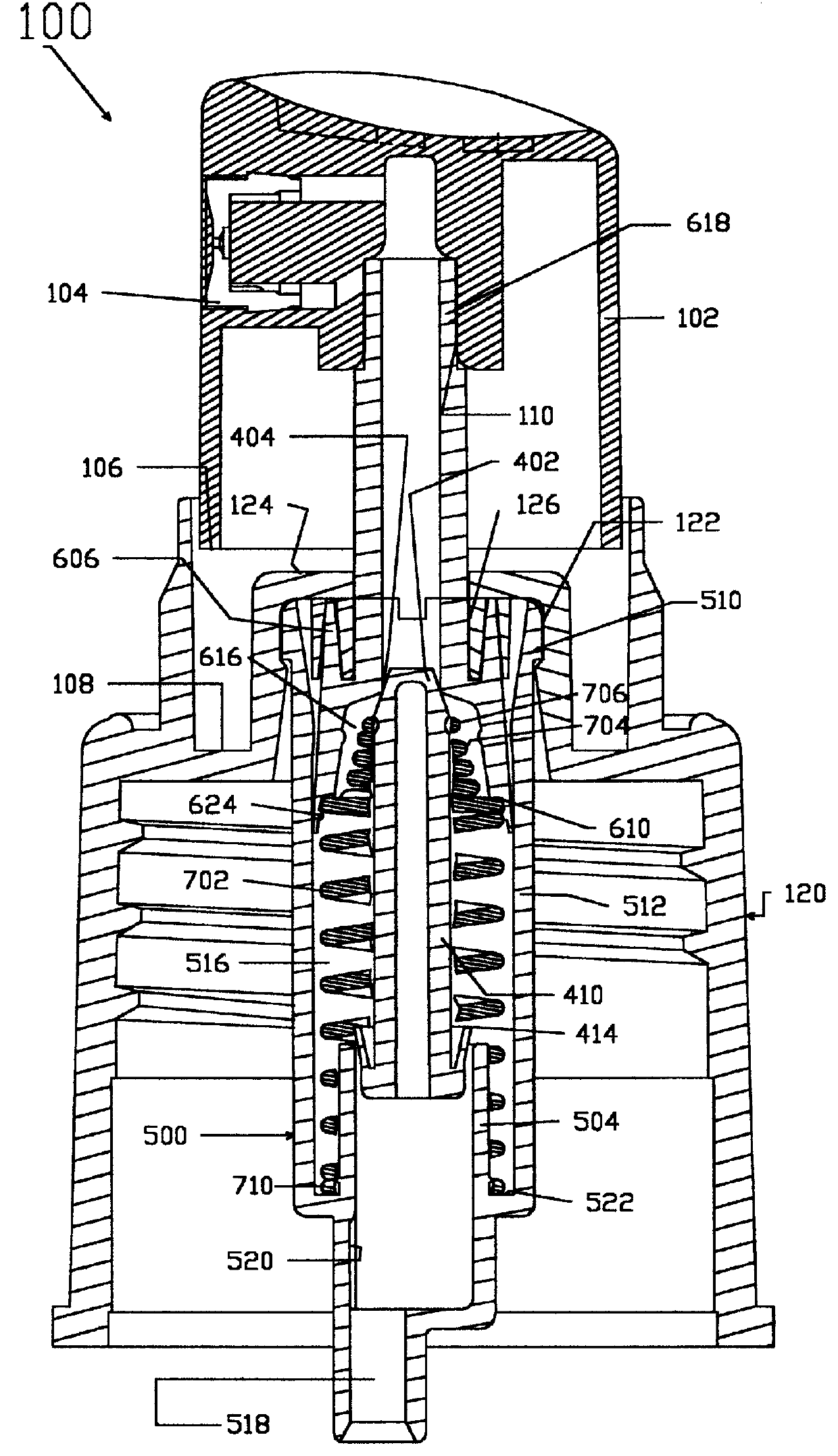
The pump spray assembly 100, illustrated in FIG. 1, includes the essential elements of the invention. Not illustrated is the container, which component is well known in the art. The spray cap 102 is provided with a convex upper surface for receiving the finger of the user, and a spray nozzle 104. The interior of the nozzle is provided with a piston receiving notch 110 dimensioned to receive the piston head 618. The spray cap 102 moveably sits within the container cap 120 that in turn is affixed to the container. The distal end of the container cap 120 is dimensioned to receive the lower edge of the spray cap 102. The downward vertical movement of the spray cap 102 is stopped by the cap ledge 124 while the upward vertical movement is controlled by the interaction between the spray cap 102 and the piston 600. The interior of the proximal end of the container cap 120 is provided with a flange indent 122 and to receive the flanged rim 510 as described hereinafter. A container seal 126 p...


PUM


Abstract

The invention relates to a manual, self-priming precompression spray pump, which employs a minimal number of different parts. The assembly includes a container for the liquid, a cap, a conventional spray nozzle unit, a valve member, a piston, a spring and a cylinder for housing the piston and providing a compression chamber. The valve upper end functions as an outlet valve and the valve lower end functions as an inlet valve. The spring is a compound spring and serves to force the valve outlet end into a constant sealing engagement with the interior of the piston, and to resist the compression movement of the piston. The cylinder for housing the piston includes an inner, concentric valve cylinder. The inner cylindrical wall has an axial length which terminates short of the chevron valve when said valve member and said piston are fully biased away from said inlet valve, whereby said chevron valve is in a position outside of said inner cylindrical wall. Thus, at this extreme position, the inlet valve is fully open for cooperation with said piston cylinder inlet end to restrict liquid flow from out of said piston compression chamber and through said piston cylinder inlet end.

Description

1. Field of the InventionThis invention relates generally to a precompression pump sprayer, and more particularly to a pump chamber priming arrangement for such sprayer and a simplified component arrangement.2. Brief Description of the Prior ArtSelf priming precompression pumps have undergone changes over the years, primarily for the purpose of producing improved valve structures, more effective self priming, improved reliability, reduced cost, and ease of manufacture. Over the years, prior art pump designs have undergone improvement and provided enhanced features.It is an object of the present invention, to provide a new concept in pump designs, in order to provide a new advancement with respect to ease of use, reliability, reduced cost, and ease of manufacture.The invention relates to a manual, self-priming precompression spray pump, which employs a minimal number of different parts. Consequently, the device is highly reliable and low in cost of manufacture. A pump sprayer of this...

Claims


Application Information

Patent Timeline
IPC IPC(8): B05B11/00B65D47/34
CPCB05B11/3073B05B11/3018B05B11/1018B05B11/1073
Inventor OLEGNOWICZ, ISRAEL
Owner OLEGNOWICZ ISRAEL
Why Eureka
Try Eureka