Precision laminar flow element for use in thermal mass flow sensors and flow controllers

Inactive Publication Date: 2000-09-19
MCMILLAN LLP
View PDF18 Cites 42 Cited by
  • Summary
  • Abstract
  • Description
  • Claims
  • Application Information

AI Technical Summary

Benefits of technology

The laminar flow element may be incorporated into a thermal mass flow sensor or flow controller such that the laminar flow element is substantially concentric with a borehole of a flow block. The laminar flow element thus can easily slide in and out of the borehole, simplifying cleaning and calibration of the precision laminar flow element. Removal and cleaning of the laminar flow element may be accomplished by persons unskilled in assembly and disassembly of thermal mass flow sensors and flow controllers. Further, calibration of the precision laminar flow element is unaffected by removal and reinstallation of the laminar flow element. Different laminar flow elements having different radial clearances may be inserted into the flow block thus providing a variety of calibrated flow ranges just by changeout of the laminar flow element.

Problems solved by technology

This is a costly type of element design.
This made it difficult, if not impossible, for one to fabricate seemingly identical capillary tube elements and obtain identical flow versus pressure characteristics.
This multiple capillary tube approach has been time consuming and costly.
This type of experimentation has proved to be quite labor intensive and has not provided a uniform laminar flow path around an outside perimeter of the laminar flow element.
Some flow measurement error inevitably resulted when the gas flow through the sensing element was compared to the gas flow through the laminar flow element.
With flow ratio errors that varied with flow rate, a non-linear characteristic could develop, thereby reducing overall accuracy.
Also, some flow inevitably traveled around the outside of the laminar flow element.
It has been very difficult, if at all possible, to insure that the laminar flow element was sufficiently centered so that a radial clearance around the outer surface of the laminar flow element remained equal.
This would likely mean that an installer would spend considerable labor time trying to "tune up" each such laminar flow element installation.
Further, it has been found that if the radial clearance varied so as to exceed a certain measurement, problems arose.
This laminar flow element design would likely be very costly to manufacture and also lack certain precision.
This design can achieve a high degree of precision but is expensive to manufacture and would be difficult to disassemble for cleaning purposes.
Manufacturing tolerances have made it commercially impractical to assure perfect radial clearance between the cantilevered plug and the flow block hole.
This variance in design has yielded grossly different results from one laminar flow element to another, making ease of calibration difficult and time consuming.
Since the laminar flow path has been destroyed when the plug is not in the center of the flow block hole, non-linearities have developed, making it difficult to calibrate a flow sensor within its accuracy requirements.
The flow path around the plug has not been even, further destroying the ability to obtain good linear results over any large flow range.
This approach has been very labor intensive and caused unnecessary calibration time.
Also, with this approach, it has been found that poor linearity resulted and the overall accuracy of a thermal mass flow sensor was significantly compromised.
Further, calibration of the precision laminar flow element is unaffected by removal and reinstallation of the laminar flow element.

Method used


Image

  • Precision laminar flow element for use in thermal mass flow sensors and flow controllers
  • Precision laminar flow element for use in thermal mass flow sensors and flow controllers
  • Precision laminar flow element for use in thermal mass flow sensors and flow controllers

Examples


Embodiment Construction

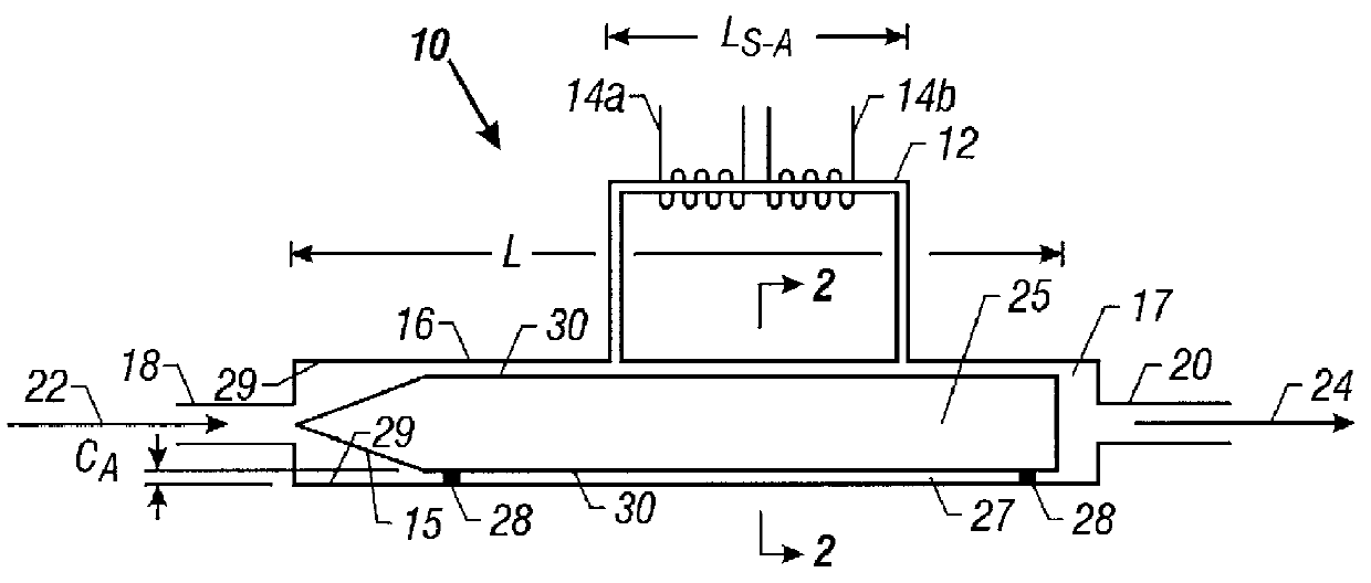
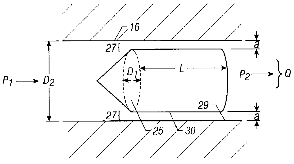
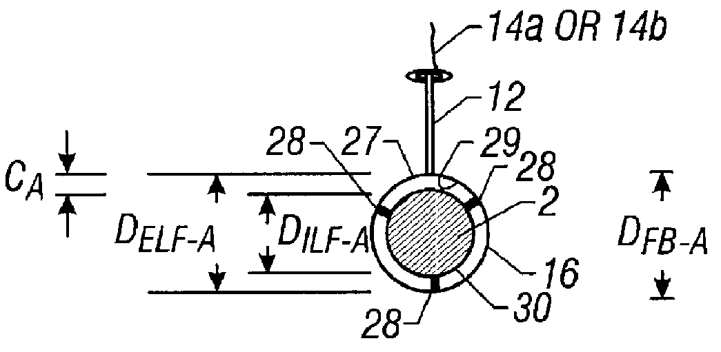
Turning now to the drawings, FIG. 1 shows a thermal mass flow mechanism 10 incorporating a low flow rate configuration of a precision laminar flow element 25 in accordance with the present invention. The thermal mass flow mechanism 10, which may be a thermal mass flow sensor or flow controller, for example, includes a sensing element 12 connected to a main flow block 16. The flow block 16 provides an inlet or entry end 18 for receiving an incoming gas flow stream 22 and an outlet or exit end 20 for providing an outgoing gas flow stream 24. The flow block 16 houses the precision laminar flow element 25. A portion of the incoming gas flow stream 22 passes through a main or laminar flow path defined by the precision laminar flow element 25 and the inner diameter of the flow block 16. Another portion of the incoming gas flow stream 22 passes through a sensing flow path defined by the sensing element 12.

In the disclosed embodiment, the sensing element 12 is a sensing tube. Two heated coi...


PUM


Abstract

A laminar flow element for use in thermal mass flow sensors and flow controllers is designed to provide a high degree of precision. The precision laminar flow element includes a laminar flow element having a generally pointed entry end for maintaining a pure laminar flow path around the laminar flow element. The generally pointed entry end serves to direct an incoming gas flow stream equally about an outer surface of the laminar flow element. In this way, the laminar flow path is uniform so as to maintain a desired flow accuracy. The laminar flow element provides a plurality of standoff pins protruding from the outer surface of the laminar flow element to maintain a substantially equal radial clearance around the outer surface. By maintaining a substantially equal radial clearance from one laminar flow element to another, the laminar flow element is highly interchangeable. The laminar flow element may also provide a plurality of slots formed in the laminar flow element to accept a relatively high incoming gas flow stream. The precision laminar flow element preserves a linear flow ratio for low and high flow rates. The laminar flow element may be incorporated into a thermal mass flow sensor or flow controller such that the laminar flow element is substantially concentric with a borehole of a flow block. Various laminar flow elements with different annular clearances may be inserted in the same borehole of the flow block to provide a variety of flow rate ranges.

Description

1. Field of the InventionThe present invention relates to laminar flow elements, and more particularly to a precision laminar flow element for use in thermal mass flow sensors and flow controllers.2. Description of the Related ArtThermal mass flow sensors and flow controllers typically incorporate a sensing tube that has two heated coils (an upstream coil and a downstream coil) wound around the sensing tube in close proximity to one another. Each heated coil is typically made of thin wire that has a characteristic of resistance change as the wire temperature changes. The heated coils direct a constant amount of heat into a gas stream flowing through the sensor tube. As the mass flow rate of the gas stream increases through the sensor tube, the sensor tube carries heat from the upstream coil to the downstream coil. The resulting temperature difference produces an increase in heat to the downstream coil and a corresponding decrease in heat to the upstream coil, thereby changing the re...

Claims


Application Information

Patent Timeline
IPC IPC(8): G01F1/34G01F1/684G01F1/40G01F15/00G01F5/00
CPCG01F1/40G01F1/6847G01F5/00G01F15/00
Inventor MCMILLAN, ROBERT D.
Owner MCMILLAN LLP
Why Eureka
Try Eureka