Wellbore shoe joints and cementing systems

Inactive Publication Date: 2000-07-04
WEATHERFORD TECH HLDG LLC
View PDF58 Cites 143 Cited by
  • Summary
  • Abstract
  • Description
  • Claims
  • Application Information

AI Technical Summary

Benefits of technology

The present invention, in certain embodiments, discloses a float system with a float collar having a top or "roof" landing baffle over an inlet of the float collar. Fluid goes around edges of ribs of the baffle to enter the float collar and a float valve therein. The baffle prevents debris (e.g. pieces of wood, a slicker suit, etc.) from clogging the float system inlet and protects the float valve from debris, rocks, gloves, eyeglasses which might prevent valve plunger movement or valve sealing, or might damage the valve.
In one aspect a plug is disclosed with a reduced inner body thickness to facilitate bending of fins on the plug's exterior in response to fluid pumped to the plug to create an alternate fluid flow path around the plug.
The present invention provides in certain embodiments a sub-sea cementing apparatus which includes a bottom plug having an opening therein, a top plug having an opening therein, and apparatus for releasably holding the bottom plug and the top plug together: the top plug, the bottom plug and the apparatus made from a resilient material. In certain embodiments the resilient material is a plastic material; a fiberglass material; a combination thereof; or any easily drillable material, including but not limited to an easily drillable metal material or an easily drillable non-metal material.
New, unique, useful, efficient and nonobvious float systems with a top landing baffle to inhibit clogging of a float valve with debris, etc;
New, unique, useful, efficient and nonobvious plugs with a nose or nose ring having a taper and a plug landing ring having a corresponding taper to effect wedge locking of the two;

Problems solved by technology

Many prior art plug set systems are complex with many moving parts, some of which are exposed to the corrosive fluids flowing up and down in the wellbore.
A variety of problems are associated with such "sub sea" release systems; e.g. parts are eroded by sand, grit, and corrosive material in various fluids; positive indication of plug release is not achieved; plugs or parts of them are not made of easily drillable material; and ocean forces on casing extending from a drilling platform to a sub-sea wellhead bend and twist the casing, inhibiting or preventing the use of certain plugs.
The disadvantage with existing sub-sea equipment is that it has been extremely difficult to control the pressure at which the bottom plug is released and even more difficult to control the pressure at which the top plug is released.
One very serious problem is when the pressure which has to be applied to release the bottom plug is so high that the top plug is simultaneously released thus severely delaying the cementing operation.
It is believed that aluminum is not the most suitable for certain sub-sea plug sets.
Furthermore, the inventors believe that since, in practice, the fluid used during circulation often contains traces of sand and minute particles, these particles often become wedged between the parts of the apparatus, piercing or damaging the surface of the aluminum, and inhibiting relative movement of the parts.

Method used


Image

  • Wellbore shoe joints and cementing systems
  • Wellbore shoe joints and cementing systems
  • Wellbore shoe joints and cementing systems

Examples


Embodiment Construction

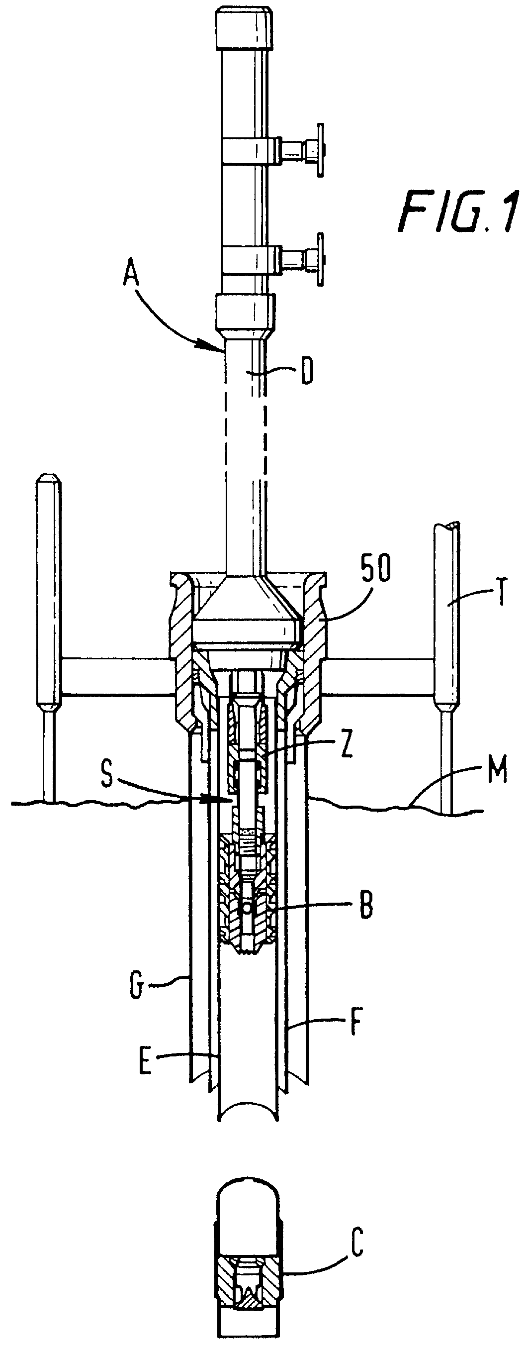
FIG. 1 illustrates a cementing system S according to the present invention which includes a plug container system A according to the present invention; a swivel equalizer Z according to the present invention; and a plug set system B according to the present invention within an innermost casing E within an internal casing F in an outer casing G. Float equipment C (e.g. but not limited to, any known float equipment, float collar or float shoe) is mounted at the bottom of the casing. Drill Pipe D extends from the plug container system A, to and through a casing hanger 50 in a sub-sea template T at the mud line M. In one embodiment the float equipment is as described in U.S. Pat. No. 5,411,054 issued May 2, 1995 entitled "Valve"; and in one embodiment the float equipment is as described in U.S. Pat. No. 5,450,903 issued Sep. 19, 1995 entitled "Fill Valve". Both these patents are co-owned with the present invention and are incorporated fully herein for all purposes.

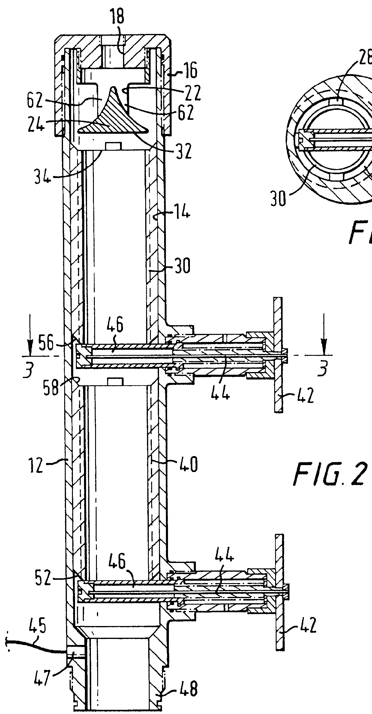
FIG. 2 shows a plug co...


PUM


Abstract

A new method for introducing wellbore cement into a wellbore shoe joint has been invented, the shoe joint having a hollow tubular body, the shoe joint containing an amount of wellbore fluid, the shoe joint disposed in a wellbore cementing system between a float shoe, guide shoe, or other flow apparatus beneath the shoe joint, and a hollow tubular member above the shoe joint, the hollow tubular member being a lower part of a wellbore tubular string of a plurality of tubular members (e.g., casing) extending from an earth surface down into a wellbore, the method including moving a wellbore wiper plug into the hollow tubular body of the shoe joint, moving the plug within the shoe joint to push wellbore fluid from the shoe joint and, in one aspect, debris in the fluid, the fluid flowing to the float shoe, guide shoe or other flow apparatus, flowing wellbore cement into the hollow tubular body of the shoe joint.

Description

1. Field of the InventionThis invention is directed to wellbore cementing systems; plug set release systems; plug containers; and swivel equalizers for well tools and apparatuses.2. Description of Related ArtDuring the construction of oil and gas wells a bore is drilled into the earth. Casing is then lowered down the bore and the annular space between the outside of the casing and the bore is filled with cement. The casing is centered in the bore by centralizers. Typically, a non-return valve, a "float valve," is mounted on or adjacent the bottom of the casing. During a typical cementing operation the annular space is first cleared by pumping circulating fluid down the inside of the casing and allowing it to flow upwardly through the annular space, then a bottom plug is placed in the casing. The bottom plug is pumped ahead of cement to separate the cement from drilling mud and other wellbore fluids and typically has wipers of elastomeric material to wipe mud from the casing so it do...

Claims


Application Information

Patent Timeline
IPC IPC(8): E21B33/13E21B34/00E21B21/00E21B21/10E21B33/03E21B33/05E21B34/06E21B33/16
CPCE21B21/10E21B33/05E21B33/16E21B34/063
Inventor GIROUX, RICHARD L.BUDDE, PETERERIKSEN, ERIKTILTON, FREDERICK T.
Owner WEATHERFORD TECH HLDG LLC
Why Eureka
Try Eureka