Patching device and method

a technology of a patching device and a hole is applied in the field of repair of hollow structures, which can solve the problems of increasing the cost of fabrication, increasing the complexity of construction, and being difficult to simply fill in the hol

Inactive Publication Date: 2000-04-04
CRAFTS BRIAN S
View PDF10 Cites 23 Cited by
  • Summary
  • Abstract
  • Description
  • Claims
  • Application Information

AI Technical Summary

Benefits of technology

It is yet another object of the present invention to provide such a wall patch which is relatively inexpensive to fabricate.

Problems solved by technology

However, if the hole is relatively large, it becomes impractical to simply fill in the hole because of the large amount of filler compound required and because the resulting weight of the filler compound may not be supported by adhesion of the cured repair material within the repair volume.
As can be appreciated, certain of these design features increase the cost of fabrication, or may add to the complexity of construction, or may be difficult for the average consumer to use successfully.
Furthermore, conventional patching components have little or no flexing capability, and this limits their application to repair openings of relatively large sizes.

Method used


Image

  • Patching device and method
  • Patching device and method
  • Patching device and method

Examples


Embodiment Construction

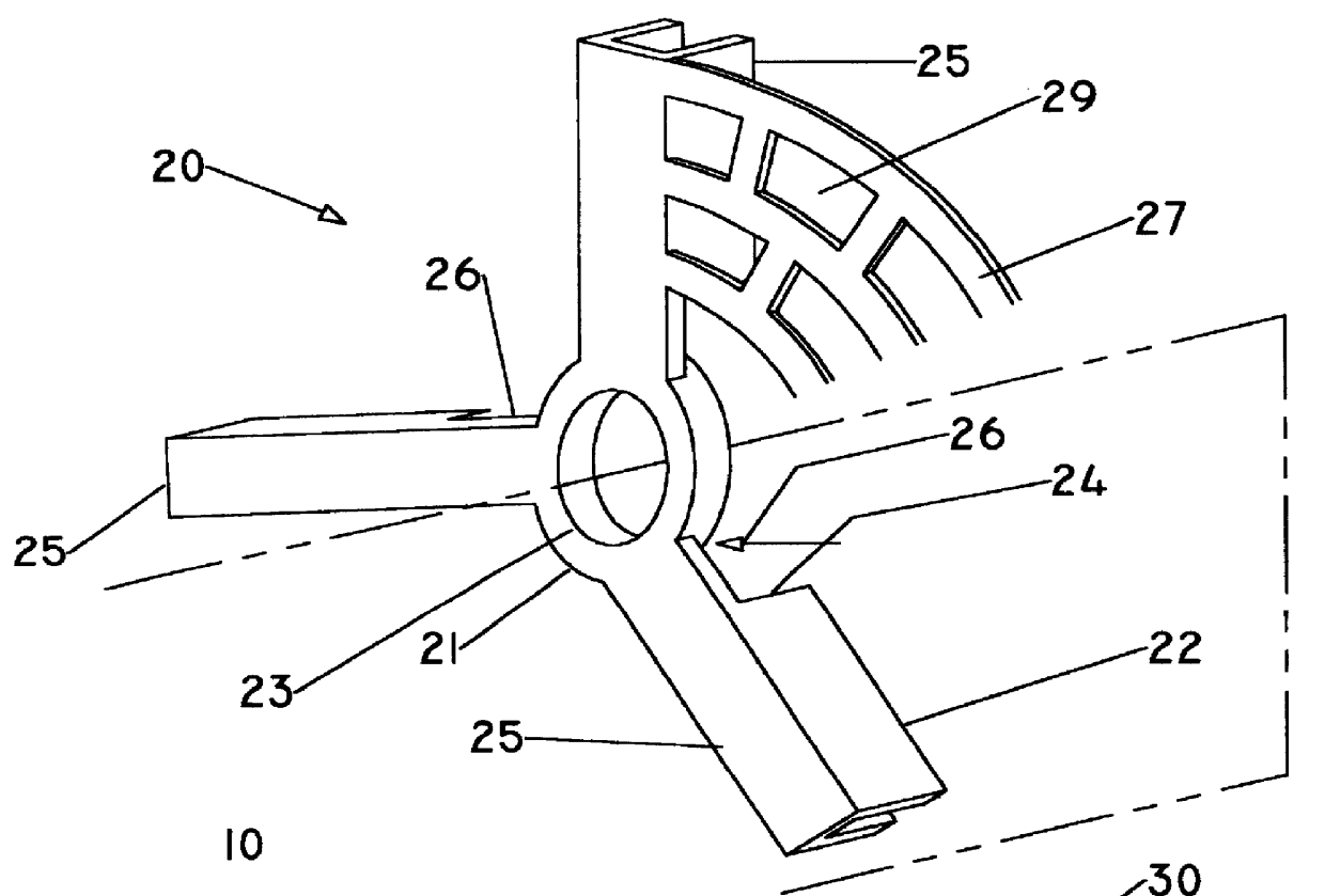
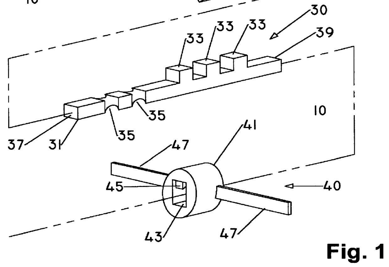
There is shown in FIG. 1 a patching device 10 comprising a plug 20, a stem 30, and locking hub 40. Plug 20 comprises a ring 21 with an axial opening 23. Although axial opening 23 is here shown as circular, other geometric shapes which allow stem 30 to pass through, can be used. Extending from ring 21 to the periphery of plug 20 are a plurality of ribs 25 flexibly attached to ring 21. In the embodiment shown, ribs 25 are generally straight but may be curved, disjoint, or spiral in shape, for example. Each rib 25 comprises a flat section 26 adjacent ring 21, and a channel section 22 comprising a U-shaped cross section. There is a shoulder 24 at the transition from flat section 26 to channel section 22. This configuration provides rigidity to rib 25 while allowing rib 25 to bend or flex at flat section 26, a feature used to advantage in the present invention, as explained in greater detail below.

In the embodiment illustrated, plug 20 is shown as comprising three ribs 25, but it should ...


PUM

PropertyMeasurementUnit
Structureaaaaaaaaaa
Sizeaaaaaaaaaa
Flexibilityaaaaaaaaaa

Abstract

A patching device suitable for use in the repair of a hollow structure which structure has a distal panel disposed from a proximal repair region. The patching device has a stem possessing a plurality of protrusions, and a collapsible plug comprising a central ring containing an axial opening to enclose the stem, and a locking hub to lock or tighten the plug against the proximal repair region. A plurality of flexible ribs extend from the central ring to the periphery of the plug. The plug has optional webs extending between adjacent ribs.

Description

1. Field of the InventionThe present invention relates in general the repair of hollow structures, such as doors and walls, and in particular to a device and method for repairing holes in such structures.2. Description of the Prior ArtThe repair of a hole made in a hollow structure, such as doors and walls, generally consist of filling the repair volume with a spreadable compound which hardens after application. If the hole is relatively small, the filler compound readily adheres to the interior of the hole and is secured upon curing. However, if the hole is relatively large, it becomes impractical to simply fill in the hole because of the large amount of filler compound required and because the resulting weight of the filler compound may not be supported by adhesion of the cured repair material within the repair volume. In such applications a backup device, or plug, is used to provide a supporting structure, to which the compound can adhere, for emplacement across the repair openin...

Claims


Application Information

Patent Timeline
IPC IPC(8): E04G23/02
CPCE04G23/0203Y10T29/49732E04G23/0207
Inventor CRAFTS, BRIAN S.SEARS, KENNETH H.
Owner CRAFTS BRIAN S
Why Eureka
Try Eureka