Slide drive arrangement

a technology of sliding drive and sliding rod, which is applied in the direction of bearings, portable percussive tools, large fixed members, etc., can solve the problem of awkward adjustment of sliding rods

Inactive Publication Date: 2000-01-18
FESTO AG & CO KG
View PDF9 Cites 30 Cited by
  • Summary
  • Abstract
  • Description
  • Claims
  • Application Information

AI Technical Summary

Benefits of technology

One object of the invention is to provide a slide drive device of the initially described type in the case of which a less dangerous and less awkward setting of the end positions of the slide is possible.
It is an advantage if the two stroke limiting means are arranged laterally on either side of the guide means extending in the longitudinal direction, it being possible for them to be provided at the two mutually opposite longitudinal sides, if there is a suitable design of the slide drive device.
The adjustable abutments may be constituted by abutment bodies, which possess an external screw thread and are received in a associated complementary screw threaded hole in a holding part provided on the slide or respectively on the principal body. By turning the abutment body it is possible for a setting movement to be produced in the direction of motion of the slide and accordingly for adjustment of the desired terminal position to be carried out. A lock nut may contribute to a reliable fixation of the terminal or end position set.
The adjustable abutments may for example be constitute by simple screws. In the case of the abutment body it may however be a question of the housing of a fluid shock absorber, which is provided in order to damp the impact of the slide on reaching the associated end position. In this case the adjustable abutment and the shock absorber associated with it may be designed in the form of a single integral unit. The latter design offers the advantage that the damping stroke remains independent of the settings of the abutment and will always be the same.

Problems solved by technology

Although the said European patent publication 0 603 459 has also disclosed a design, in which the adjustable abutments are arranged directly adjacent to one another, they are however still both on the moving slide and accordingly on one longitudinal side of the principal housing so that adjustments are still awkward to perform, more especially since movements of the hands necessary for adjustment still have to be performed from opposite sides on the abutments.

Method used


Image

  • Slide drive arrangement
  • Slide drive arrangement
  • Slide drive arrangement

Examples


Embodiment Construction

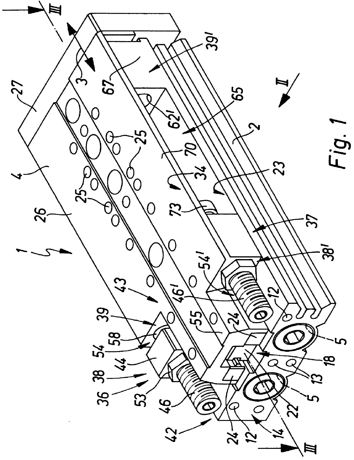
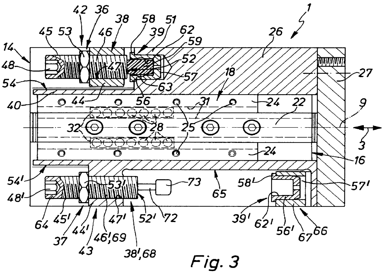
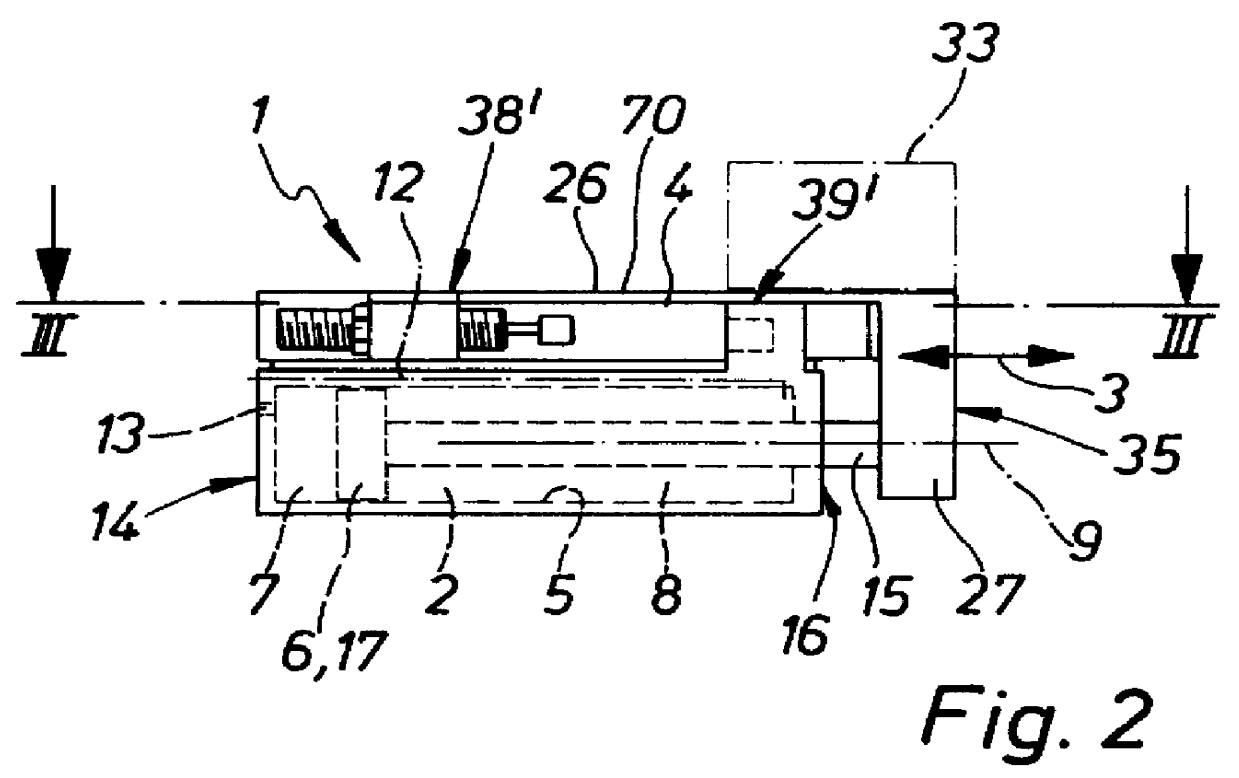
The slide drive device 1 illustrated in the drawing comprises an elongated principal housing 2 and a slide 4 running thereon in the longitudinal direction as indicated by the double arrow 3 in a reciprocating manner.

In its interior the principal housing 2 possesses two housing chambers 5 arranged adjacent to each other at a distance apart and extending in the longitudinal direction 9, in which chambers a respective axially running piston 6 is provided. The piston 6 sealingly subdivides the associated housing chamber 5 into two working spaces 7 and 8 which communicate with pressure medium ducts 12 and 13 as are diagrammatically indicated in FIG. 2, such ducts opening exteriorly on the principal housing 2. It is preferred for the corresponding openings to be arranged in a common end face of the principal housing 2, for example at the rear end side 14. By way of pressure medium lines connected with the openings it is possible for a fluid pressure medium and more especially compressed a...


PUM

PropertyMeasurementUnit
Fractionaaaaaaaaaa

Abstract

A slide drive device has a principal housing, in which at least one actuating element able to be driven linearly is arranged. Externally on the principal housing there is a slide kinetically coupled with the actuating element. Two stroke limiting means render possible a variable preset of the two end positions of the slide and each comprise an adjustable arranged on the one part and a counter-abutment arranged opposite to same on the other part. The one adjustable abutment is arranged on the slide and the other adjustable abutment is located on the principal housing. Both abutments are provided in end regions facing in the same axial direction, on the slide and, respectively, on the principal housing.

Description

The invention relates to a slide drive arrangement comprising a principal housing, in which at least one actuating element able to be driven for linear motion is arranged, a slide arranged externally on the housing and kinetically coupled with the at least one actuating element, said slide being able to be guided by means of a guide means in relation to the principal housing between two end positions linearly, and two stroke limiting means acting between the principal housing and the slide for variably presetting the two end positions of the slide, such limiting means each comprising an abutment arranged on one part and able to be set in the direction of motion of the slide and a counter-abutment arranged opposite to same on the other part.THE PRIOR ARTA slide drive arrangement of this type is for instance disclosed in the European patent publication 0 683 010 A1. Its principal housing contains one or more actuating elements in the form of pistons, which are kinetically coupled by m...

Claims


Application Information

Patent Timeline
IPC IPC(8): B23Q1/58B23Q16/00B23Q1/25F16C29/04F02B75/02F15B15/14F15B15/24
CPCB23Q1/58B23Q16/001F15B15/24F16C29/04F02B2075/025F16C2322/39
Inventor STOLL, KURTMODINGER, UWEWALDMANN, DIETER
Owner FESTO AG & CO KG
Why Eureka
Try Eureka