Determining position of magnetic resonance data with respect to magnetic field sensors

a magnetic resonance data and magnetic field technology, applied in the direction of diagnostic recording/measuring, measurement using nmr, instruments, etc., can solve the problems of deteriorating significantly the inverse estimate, affecting the workflow, and errors in the localization of brain activity

Active Publication Date: 2022-11-17
AALTO UNIVERSITY FOUDATION SR
View PDF1 Cites 0 Cited by
  • Summary
  • Abstract
  • Description
  • Claims
  • Application Information

AI Technical Summary

Benefits of technology

The present invention provides a method for magnetic resonance imaging that includes generating data with sensors arranged around an imaged target volume and determining a mapping between the image frame and sensors frame to ensure the data is in agreement with the sensitivity profiles. This results in a more accurate and reliable image of the target area. The technical effects include improved image quality, reduced image noise, and improved accuracy of target localization.

Problems solved by technology

Determining the position of data in different coordinate systems is a common problem in medical imaging.
Inaccuracies in the co-registration distort both the conductor model and the source model of the neuromagnetic problem, causing errors in the localization of brain activity.
The total co-registration error can be up to 10 mm and, depending on assumptions in the source modeling, it can significantly deteriorate the inverse estimates.
Improving the co-registration accuracy in a systematic fashion has thus far involved external equipment, further complicating the workflow.

Method used


Image

  • Determining position of magnetic resonance data with respect to magnetic field sensors
  • Determining position of magnetic resonance data with respect to magnetic field sensors
  • Determining position of magnetic resonance data with respect to magnetic field sensors

Examples


Embodiment Construction

Definitions

[0015]Magnetoencephalography (MEG): a method to localize electrical brain activity from magnetic field measurements outside the head.

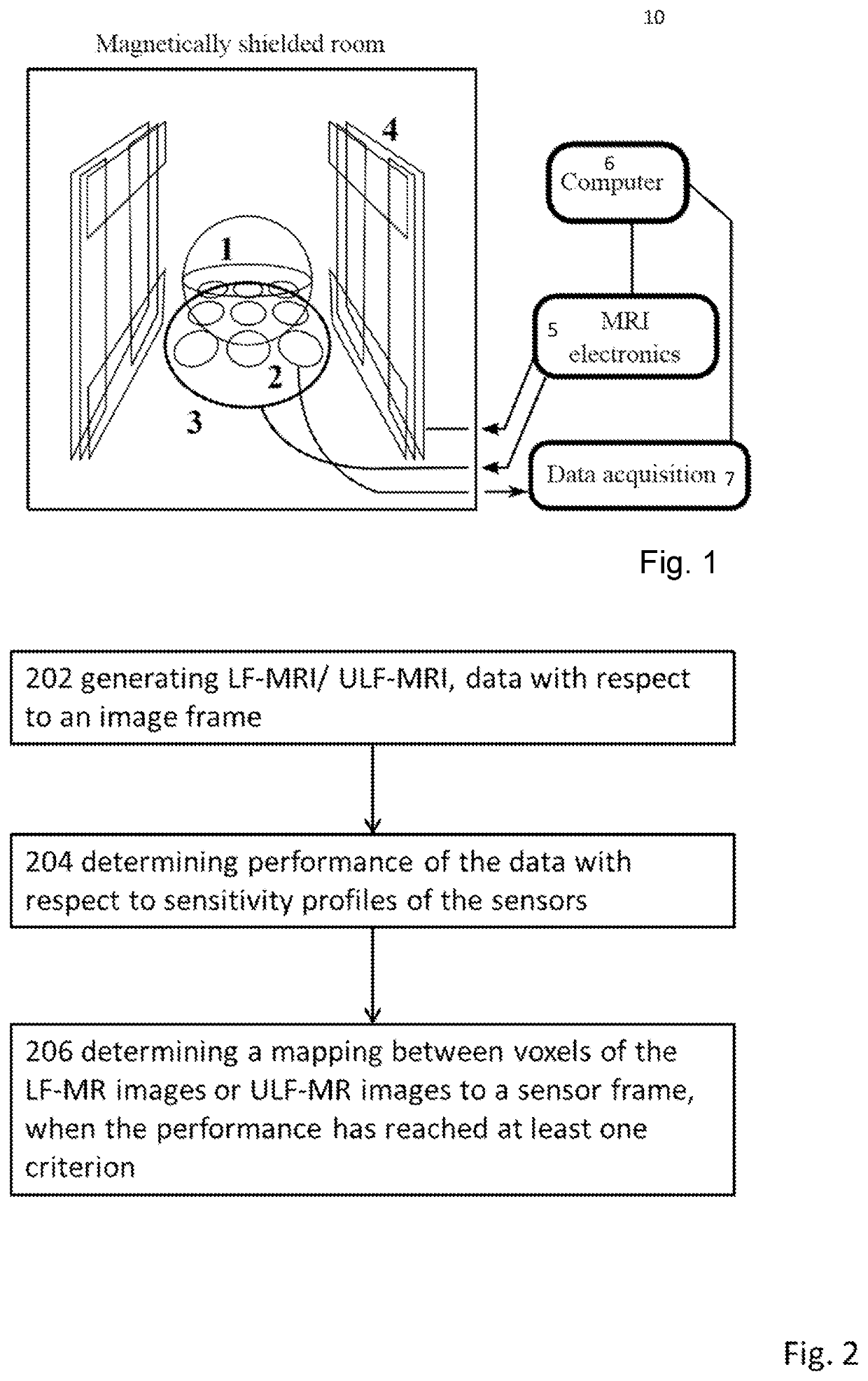
[0016]Magnetic resonance imaging (MRI): a medical imaging technique to form a three-dimensional image of an object based on controlling nuclear spins in the imaged matter and measuring their magnetic field.

[0017]MRI signal: the magnetic field or a quantity related to the magnetic field of precessing nuclear spins.

[0018]Measurement sequence: a set of the magnetic field pulses affecting the spins to provide data for image reconstruction

[0019]Image reconstruction: a method for converting the magnetic field data of the spins to a three-dimensional image.

[0020]Imaging phantom or target volume: an object positioned in a field of view of MRI system. The object provides MRI signal when being measured.

[0021]Field of view: imaging volume of which the MRI image is taken by generating magnetic field gradients to the volume.

[0022]Larmor frequency: the fr...


PUM


Abstract

According to an example aspect of the present invention, there is provided generating, Low-Field-Magnetic Resonance Imaging, LF-MRI, or Ultra-Low-Field Magnetic Resonance Imaging, ULF-MRI, data with respect to an image frame, determining a sensorwise agreement of the data with determined sensitivity profiles, and determining a mapping between the image frame and a sensor frame, such that the sensorwise agreement has been fulfilled.

Description

FIELD[0001]The present invention relates to determining the position of magnetic resonance data with respect to magnetic field sensors.BACKGROUND[0002]Determining the position of data in different coordinate systems is a common problem in medical imaging. For instance, in magnetoencephalography (MEG), neuronal activity estimated from magnetic field measurements with an array of sensors outside the head must be known in the same coordinates as the brain structure. As the overall precision of MEG increases, accurate knowledge of the brain conductivity structure with respect to the magnetic field sensors becomes more and more important for modeling the neuronal fields at the sensors. Independent of this, accurate positional information of the brain anatomy is also essential when setting constraints for reconstructing the neuronal sources. This information usually comes from magnetic resonance (MR) images of the subject's head. Because the brain structure is imaged in a different device...

Claims


Application Information

Patent Timeline
IPC IPC(8): G01R33/44G01R33/48G01R35/00G01R33/32
CPCG01R33/445G01R33/4808G01R35/00G01R33/32G01R33/326G01R33/58A61B5/0035
Inventor ZEVENHOVEN, CORNELISMÄKINEN, ANTTIILMONIEMI, RISTO
Owner AALTO UNIVERSITY FOUDATION SR
Why Eureka
Try Eureka